3GPP and CTIA test specifications now require 3D over-the-air (OTA) measurements of 5G millimeter-wave (mmWave)-capable devices under extreme temperature conditions (ETC). 3GPP requirements for RF conformance testing of user equipment (UE) are designed to avoid problems that would impair the functioning and performance of wireless networks. These 5G OTA test systems need to be optimized for airflow and thermal efficiency.
Up until 5G FR1 (frequencies below 7.125 GHz), all 3GPP conformance evaluations were based on conducted measurements, connecting RF cables directly at the antenna ports of the device under test (DUT). A major change, however, occurred in 5G, with the FR2 frequency range in the mmWave spectrum (FR2-1: 24.25 GHz to 52.6 GHz; FR2-2: 52.6 GHz to 71 GHz).
As UE FR2 antennas are dynamic beam-steering arrays, the conducted approach became irrelevant, as the overall performance of a DUT is intrinsically linked to the antenna system. In addition, the high level of integration of arrays and RF front ends enabling the operation of such technologies makes it practically impossible to reliably connect cables at adequate points.
OTA assessment appeared as the correct and most straightforward approach. Far-field (FF) spherical measurements in anechoic chambers became the basis for almost all sorts of tests for FR2 UE. To measure in FF for OTA assessments, the quiet zone (QZ) needs to be at least the size of the DUT aperture. This requires either a small device or the exact location of the device antenna aperture. Because a UE can be large (such as mobile phones, tablets and laptops) and manufacturers are reluctant to disclose the exact location of antenna elements, the “black box” approach was adopted, where the DUT is placed in the QZ of the FF measurement setup.
As a result, the compact antenna test range (CATR) was adopted by 3GPP as the reference test environment due to its capability to offer a large QZ within a confined space. Because UEs are utilized in diverse environmental conditions, spherical OTA measurements at ETC, ranging from –10°C to 55°C, also became part of the 3GPP UE RF conformance test specifications. These temperatures can influence the active electronics in the DUT and affect the beamforming performance.1
Designing a CATR, which allows dual-axis rotations of the DUT for performing accurate FF 3D measurements under ETC, sounds simple but is a complex engineering problem. The complexity is increased when considering the need for high-speed testing, and hence fast temperature ramps, while protecting the anechoic chamber and positioning system from possible damage due to very high or very low temperatures and maintaining the shielding effectiveness of the chamber at a high level.
The ETC OTA system
These testing requirements pose a number of challenges, including many complex conditions. Innovation was necessary, which resulted in a number of patents for multiple components in the final ETC OTA solution.
One of the challenges is that exposure to a wide positive and negative temperature range can create severe damage, particularly to the absorbers in an anechoic chamber as well as to the motors in a 3D positioner, which would alter their operation. To protect these devices, the DUT needs to be enclosed in a thermal compartment within the OTA chamber itself, containing the extremely cool or hot air as hermetically as possible, while the rest of the chamber is mostly maintained at about ambient temperature.
One key upside of limiting the volume of extreme temperature is the reduced amount of energy and air volume that must be provided into the thermal compartment to stabilize at the ETC condition, hence the higher speed to reach the target temperature.
However, major difficulties arise from this concept. First, the thermal enclosure must be RF-transparent enough to limit its impact on the QZ uniformity as well as on the DUT radiation properties. On the other side, the enclosure needs to be stable enough to withstand potentially increased inner air pressure due to the temperature airflow while isolating the hot or cold air from its surroundings.
In addition, all mechanical parts of the thermal enclosure, as well as the air pipes that connect to it, must still allow the full 3D movement of the dual-axis positioner and the DUT while keeping air-tightness. Last but not least, the air hoses must be run in and out of the chamber through RF-shielded walls without compromising the shielding effectiveness at a high level.
All of these considerations lead to a system concept based on the R&S ATS1800C compact 3GPP-compliant OTA chamber for 5G NR mmWave signals. It was enhanced with an airflow chain, consisting of compressed dry air in a wide range of temperatures provided by an external climate machine, called Thermostream, as shown in Figure 1. This device is connected to power and a central compressed air supply and provides the required air volume at certain set minimum and maximum temperatures to the air inlet of the anechoic chamber. Running the air pipes through the shielded chamber walls requires the design of RF-filtered air feedthroughs.
Once inside the shielded chamber, the hoses connect to an air rotary joint to support airflow through the elevation axis of the combined-axis azimuth-over-elevation positioner while not limiting its angular movement capabilities. The tubes are then run along the elevation swing and connected to the thermal enclosure. The azimuth rotation stage of the positioner is guided in an isolated manner into the thermal compartment to allow full rotation of the DUT in the second axis. This allows a full 3D assessment of the DUT under ETC.
The upper dome of the thermal compartment is made of RF-transparent Rohacell material and closes via an air-sealed locking ring. The dome material allows for high-quality RF measurements with the dome in place, as its permittivity is close to air; hence, the impact of the dome on the RF radiation to be measured is kept to a minimum. The shape of the dome, the thickness of its wall and the processing of the material were carefully selected to find the right tradeoff between minimizing RF perturbations while allowing for air-tightness and robustness of the dome to withstand a possible internal air pressure increase.
Once inside the thermal enclosure, the air is guided using a patented diffusor structure. This ensures a fast and equalized distribution of temperature in the enclosure, accelerating the convergence toward stable temperature conditions. After using the energy of the air provided in the thermal compartment, the air exhausts through pipes in the same way via its own isolated path in the air rotary joint and separate exhaust air feedthrough out of the chamber, where the hose ends at a specially designed silencer to reduce noise exposure.
ETC OTA solution performance
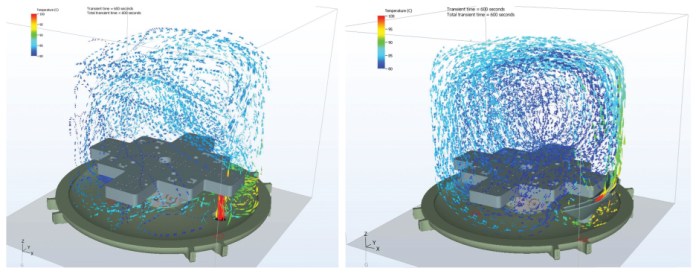
Multiple optimization rounds involved electromagnetic simulations as well as airflow and thermal simulations to optimize the air distribution within the thermal enclosure. Figure 2 depicts airflow simulations under different conditions. Many prototypes and hundreds of hours of testing led to an easy-to-handle ETC OTA solution in which devices of different sizes can be tested in full 3D in a wide temperature range using a very compact test environment.
With this setup, temperature changes well beyond the 3GPP-required limits can be achieved in a short time using an airflow rate of up to 700 liters/minute. At that flow rate, a temperature change between 85°C and –40°C is possible in 10 to 14 minutes within a 50-liter ETC compartment where cooling naturally takes slightly longer than heating.

Figure 2: Temperature and airflow distributions calculated within a 50-liter thermal enclosure with a direct pipe entry (left) and an added diffusor (right) (Source: Rohde & Schwarz)
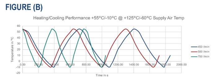
Even without the immediate need for a 125-Kelvin temperature window, having it available is an advantage, as the additional temperature headroom supports very fast temperature ramps when testing in the 3GPP-specified temperature range. A temperature change between –10°C and 55°C can therefore be achieved in less than three minutes in the same thermal enclosure size. Cooling over this full 3GPP temperature window takes only about 40 seconds longer, as shown in Figure 3.

Figure 3: Temperature cycle times obtained with different airflow rates in a 50-liter thermal enclosure over a full temperature range (a) and 3GPP temperature range (b). (Source: Rohde & Schwarz)
5G communications have supported the deployment of mmWave antenna array beam-steering technologies at an unprecedented commercial scale. As per 3GPP2 and CTIA3 test specifications, 5G mmWave-capable mobile phones must undergo a large number of tests to guarantee adequate performance.
The defined measurement methodology relies on FF OTA assessments in CATR. As temperature influences the active electronics in the wireless devices and hence the beamforming characteristics, OTA measurements are also required in ETC ranging from –10°C to 55°C, as per 3GPP test specifications. For these tests, an innovative CATR test solution with an embedded thermal compartment is required to meet conformance testing needs.
References
1Schoenholz, B.L., Downey, J.M., & Piasecki, M.T. (2022). “Design of a Thermal Testbed for Metrology of Active Antennas.” Antenna Measurement Techniques Association Symposium (AMTA).
23rd Generation Partnership Project. (June 2022). “3GPP TS 38.521-2 V16.12.0.” Technical specification.
3CTIA. (February 2022). “Test Plan for Wireless Device Over-the-Air Performance, v4.0.”
Advertisement
Learn more about Rohde & Schwarz


