BY ARTHUR PINI
Consultant. Teledyne LeCroy
arthurapini@gmail.com
The real world of electronic measurements is not a nice place. Noise, interference, and unexplained offsets wreak havoc with you data acquisition. Take for example the measurement of an ultrasonic range finder shown in Fig. 1 .
The range finder emits a 40-kHz burst and senses a reflection of that emitted pulse. The oscilloscope screen in Figure 1 shows a 10-segment acquisition recorded using an instrumentation microphone with a bandwidth of 100 kHz. There are 10 repeated measurements included in that trace each taking one horizontal division of the display. It’s pretty easy to see the transmitted pulses but the location of most of the echoes are buried in the ambient noise.
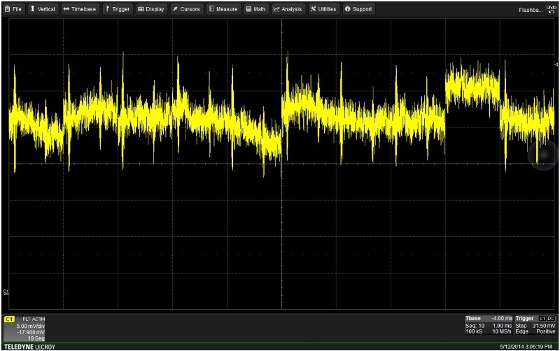
Fig. 1: The acquired acoustic signal from a 40-kHz ultrasonic range finder. Ambient noise overrides most of the echoes and interferes with the ability to make a measurement.
This is not an atypical measurement problem, extracting the desired signal from background interference. Luckily, many midrange oscilloscopes — like the Teledyne LeCroy HDO series — provide all the tools necessary to clean up this signal and make useable measurements. Here are the five steps used to solve the problem:
1. Limit the acquired bandwidth to match that of the signal you are interested in
The device uses a ceramic transducer that as a relatively narrow bandwidth. The microphone has a 100 kHz bandwidth and is ‘wide open’ to picking up ambient room noise like air conditioners, conversation, and copy machines. Luckily, you don't have to shut down these office necessities to make you measurement. You can filter the acquired signal and reduce the measurement bandwidth to that of the device being measured. In this case the signal was band pass filtered with a lower cutoff frequency of 35 kHz and an upper cutoff frequency of 45 kHz. The result is shown in the second trace from the top, F1, in Fig. 2 . The filtered trace is quite a bit ‘cleaner than the one we originally acquired. The transmitted burst and the echoes are easily seen. 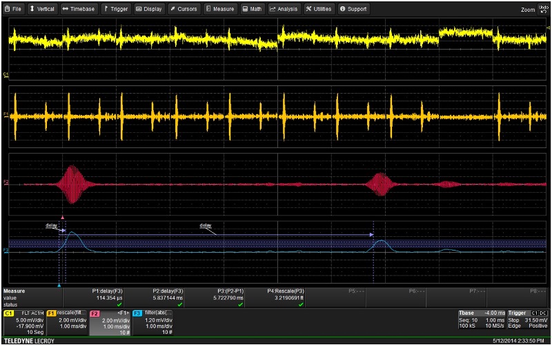
Fig. 2: By applying band pass filtering, averaging, and AM detection it is possible to improve measurement reliability and accuracy. Parameter math helps measure the delay between pulses and rescale delay to distance.
2. Use averaging to help eliminate uncorrelated noise .
The ten acquired segments of the sequence mode acquisition are from an identical source. We can further reduce noise by averaging those acquisitions. When averaging is turned on the scope is smart enough to average all ten segments. The resulting waveform, in trace F2 (second from the bottom), clearly shows not only the transmitted pulse but also multiple echoes as the signal baseline is quite clean.
3. Demodulate the AM signal to make measurements more accurate
Verifying that range measurement of the device involves measuring the time delay between the transmitted pulse and the echoes. It is difficult to make that measurement on the amplitude modulated waveforms we have acquired. The best approach is to demodulate the waveform and extract the modulation envelope.
Trace F3 in Fig. 2 is the demodulated envelope of the signal in F2. This was calculated by taking the absolute value of the trace in F2 (full-wave rectification) and then low pass filtering the result with a cutoff frequency of 10 kHz. The resultant waveform is the modulation envelope that exactly tracks the peaks of the original 40-kHz carrier. We can easily make timing measurements on this waveform.
4. Use parameter math to create a custom measurement
Measuring the time delay between two pulses on the same trace can be done with cursors but measurement parameters are generally much more accurate. There is not a parameter that will measure the time delay between these pulses directly but we can create one with parameter math. First measure the delay from trigger to the mid-amplitude point of the transmitted pulse envelop (P1) . Then, using parameter gates isolate the primary reflection, measure the time delay from the trigger to the primary echo (P2). Parameter math in P3 takes the difference which is the delay between the transmitted and reflected pulse.
5. Use parameter math to rescale delay into distance
The distance between the range finder and its target is computed by multiplying one half the time delay we have measured, by the velocity of sound. Parameter math includes a rescale function which is used in P4 to multiply the measured delay time by 562.5 to obtain the range in feet.
There you have a simple case of a measurement based on the application of the signal processing and measurement tools available in an oscilloscope.
Advertisement
Learn more about Teledyne Lecroy


