Some design considerations for high-brightness LEDs
While designing with LEDs was once considered a trivial task, the advent of HBLEDs has added a range of new challenges
BY CARY ESKOW
Avnet LightSpeed
Phoenix, AZ
http://www.em.avnet.com/LightSpeed
In years past, LEDs were primarily considered as indicator lamps, low-level backlights for small LCD panels, and novelties. They were also trivial to design with, requiring little more than knowledge of the LED’s forward voltage (Vf ) and Ohm’s law. With the recent introduction of high-brightness LEDs (HBLEDs), the landscape has changed dramatically. HBLEDs are tremendously bright, and the associated system-level design challenges can be considerable.
Heat issues
Let’s start with heat. Like all simple diodes, LEDs are constructed with p-type semiconductor materials doped to have an excess of positive charge carriers (holes), and n-type materials doped to have an excess of electrons. When a forward voltage is applied across the LED, mobile electrons traverse the p-n interface and “fill” holes on the p side, falling into a lower energy level. Ideally, the excess energy from each electron’s transition results in the spontaneous emission of a photon (radiative recombination).
That doesn’t always happen, though. Lattice dislocations, foreign atoms, and other defects present in the materials lead to nonradiative electron-hole recombination events that serve only to vibrate the lattice atoms. As you learned in physics, vibration translates into heat. HBLEDs can get very hot.
Heat isn’t a problem for a traditional incandescent bulb because about 85% of the energy applied is conveniently radiated out in the form of infrared energy. Not so with an HBLED, because the die produces light in a narrow output spectrum. Spectrographically speaking, an HBLED designed to generate 555-nm (green) light will produce very little else.
As a result, visible HBLEDs have no opportunity to radiate excess heat. So, to ensure that an HBLED’s maximum internal junction temperature isn’t exceeded, heat must be conducted out. If you’re not mindful of the die’s temperature, bad things happen: the LED’s luminous efficacy decreases, its color shifts slightly, and its mean time to failure (MTTF) will be considerably reduced.
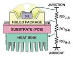
To determine the proper heat sink, you’ll need to know the device’s maximum allowable junction temperature (Tjunction ), the input power (Pd ), the maximum ambient temperature (Tambient ) under which it will operate, and the thermal resistances of all the interfaces from the die to the heat sink material (see Fig. 1 ). Their relationship is given by the equation:
RΘheatsink to ambient =
(Tjunction − Tambient ) /
(Pd − RΘjunction to substrate − RΘsubstrate to heatsink )
You’ll need a heat sink or metal case with a thermal resistance equal to or less than RΘheatsink to ambient .

Fig. 1. In this basic thermal model of an HBLED assembly, the thermal-resistance elements of the heat dissipation path are clearly visible
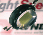
This level of detail isn’t always necessary if you design with an HBLED that has an integrated heat sink, like the Dynasty series HBLED (see Fig. 2 ). It’s constructed of 16 medium-power HBLED die attached radially to a cylindrical thermal slug, and placed in a metal case with a threaded base. The HBLEDs are encapsulated in a cylindrical lens, which causes light to radiate out on all sides of the package, like a miniature lighthouse. Because they are ruggedized, waterproof and can be field-replaceable (by unscrewing it from a socket), we often see these used in consumer lighting and medical applications.

Fig. 2. A Dynasty HBLED has a built-in heat sink to simplify design.
Power issues
Beyond thermal management, another important consideration is the HBLED’s power supply. Since all LEDs are current-driven devices, you need to regulate current, either with a series resistor or a current-controlled buck or boost regulator.
Series resistors are less expensive, but there are drawbacks. Resistor schemes only work with known, fixed operating voltages, and in terms of power are inefficient. Furthermore, because the forward voltage drop of an LED can only be specified within a range (called a bin), in some applications the specific resistance value for each of set of LEDs may need to be determined at production time, if uniformity of intensity is important.
Many analog IC manufacturers including Maxim, National Semiconductor, Texas Instruments, STMicroelectronics, and ON Semiconductor have excellent solutions for high-efficiency buck and boost type current-controlled regulators.
When LEDs are directly driven from an ac mains rather than a dc source, driver circuits are a little complicated, because a high voltage source needs to be lowered, rectified and current-controlled. One exception to this is the Acriche series HBLED (see Fig. 3 ), which connects directly to the ac mains without an external driver. Inside the package, two long strings of HBLED die are wired in reverse parallel. This allows it to operate on both phases of the ac line, and the strings’ total forward voltage is very high. A simple resistor is needed to select between 115- and 230-Vac operation.

Fig. 3. The Acriche HBLED runs directly of off ac mains.
Ready to light
When time-to-market is critical, there’s yet a third option. The large illuminated letters you see on the outside of commercial buildings are called “channel lettering”. You may be surprised to learn that most of those letters are illuminated with neon tubes. When illuminated channel lettering was first developed, neon was the only lighting product which could light interior surfaces evenly and be bendable to conform to the contours of the letters.
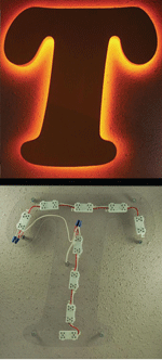
Now channel lettering can be easily lit using LEDs. A typical LED product that makes this possible is sold in 100-ft reels, and consists of 10 HBLED clusters spaced every few inches along a two-conductor cable (see Fig. 4 ). The installer simply cuts the length needed and attaches it with screws or the double-sided adhesive on the back of each module. Finally, the two wires are connected to a 12-Vdc source.
Such lighting

Fig. 4. HBLEDs now come in strips that simplify channel lettering and other strip-lighting applications.
can also replace fluorescent tubes in vending machines, architectural cove lighting, and marine applications. It’s offered in white, red, green, blue, yellow, and orange. ■
Advertisement
Learn more about Avnet Electronic Marketing


