BY NICHOLAUS R. BILLIG
Product Marketing Manager
AVX, www.avx.com
High-reliability capacitors specifically designed for use in harsh, high-temperature power conversion applications— including military, aerospace, and energy applications — are always in demand. Manufacturers who build equipment for such applications have typically relied upon components that meet stringent military specifications to ensure high-reliability performance under harsh environment conditions. Emerging markets like downhole oil and gas exploration area are increasingly demanding capacitors capable of high-reliability operation in temperatures up to 200°C, which is well in excess of the -55° to +125°C MIL-spec temperature range. Aluminum electrolytics rated at 135°C and stacked ceramics rated at 200°C are available today; however, the performance of these two capacitor technologies at extreme temperatures is often quite different. So, it is critical for OEMs to work closely with their suppliers when specifying capacitors for applications with operating temperatures outside of the MIL-spec range, as existing documentation for the devices may have information about extended temperatures.
Military temperature requirements
Current military, aerospace, and space specifications include a Qualified Vendor Listing (QVL) and Qualified Product Listing (QPL), as well as a specification for typical capacitance change across the temperature range of -55° to +125°C. The two most popular dielectrics for high reliability MIL-spec capacitors are X7R and C0G (NP0). The X7R dielectric exhibits a capacitance change of ±15% across the -55° to +125°C, the C0G(NP0) ±30 ppm/°C. At present, drawings commonly used for stacked ceramic capacitors in military, aerospace, and space applications include MIL-PRF-49470, DSCC 87106, and DSCC 88011.
Emerging markets such as the “downhole” oil and gas exploration sector have forced passive electronics suppliers to raise the temperature capabilities of stacked switch mode power supply (SMPS) multilayer ceramic capacitors (MLCC) and aluminum electrolytic capacitors—the two most popular passive components employed. Present-day oil drilling equipment can reach depths of seven to nine miles underground, at which point temperatures can reach 200°C or higher. The most common high-temperature specification range for SMPS capacitors is currently 125° to 200°C.
SMPS MLCCs tend to exhibit rugged, high temperature performance that is far better suited to applications in the demanding oil exploration market than aluminum electrolytic capacitors. MLCC dielectrics capable of temperatures up to 250°C are currently under development.
New stacked ceramic dielectric formulations
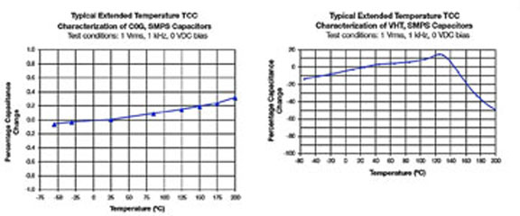
Stacked ceramic capacitors offer stable, reliable extended temperature characterizations across a range spanning -55° to 200°C. The C0G dielectric is the most stable for this market and actually exhibits an increase in capacitance of 0.3% at the high temperature benchmark of 200°C, whereas very-high-temperature (VHT) dielectrics (for example, X7R) exhibit a decrease in capacitance of -50% at 200°C. However, although X7R dielectrics experience a drop in capacitance at such high temperatures, they also offer a stable drop that can easily be characterized and plotted (see Fig. 1 ).

Fig. 1: Typical extended temperature characterization of C0G vs. VHT SMPS capacitors.
Stacked ceramic vs. aluminum electrolytic
Aluminum electrolytic capacitors are typically an electronic design engineer’s first choice in an SMPS application. Electrolytics offer extremely high capacitance per unit of surface area on the PCB and the cost for electrolytics is much lower than stacked ceramic capacitors. Electrolytics provide high capacitance per unit of volume from an extremely thin dielectric aluminum oxide (Al2 O3) layer deposited onto an aluminum metal foil, which is etched to increase surface area and capacitance.
Stacked ceramic components use a Pd/Ag precious metal electrode system (PMS) along with either a mixture of titanates like titanium dioxide (TiO2) and additives for C0G Class 1 dielectric or barium titanate (BaTiO3) plus silicates and/or aluminum oxide for the X7R Class 2 dielectric, both of which are Ag terminated. Ceramic capacitors have limitations regarding the thickness of the dielectric layer due to the limited tension strength of the ceramic, so they have a multilayer structure and are stacked to increase capacitance.
There are some drawbacks to using electrolytics. Aluminum electrolytic capacitors are polarized, and if the polarity of an electrolytic is reversed, it will overheat, potentially causing a catastrophic failure by exploding. Ceramic capacitors exhibit no sensitivity to the polarity of an applied voltage.
Electrolytic capacitors exhibit significant changes in capacitance (usually an increase) at elevated temperatures, along with higher leakage currents, especially above 105°C. And, operational life is reduced at higher temperatures. Stacked ceramics maintain their X7R or NPO stability at temperatures of 200°C and higher.
An aluminum electrolytic capacitor’s dielectric will heal itself after an overvoltage is applied – an advantage. However, electrolytics, even at benign storage temperatures, exhibit an increase in DC leakage current over time due to impurities in the material.
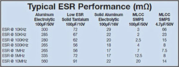
Stacked ceramic capacitors generally perform much better at high frequency. Typically, an electrolytic capacitor exhibits a higher ESR than a ceramic one, especially at high frequencies. An engineer will sometimes place many electrolytic capacitors in parallel to lower the ESR. At a typical switching frequency of 100 kHz, a 100-µF 50-V electrolytic capacitor might have ESR of 280 mΩ, whereas the same value stacked ceramic capacitor would have just 2.5 mΩ (see Table 1 ).

Table 1: Typical ESR Performance (mΩ) of capacitors with various dielectric materials
Applications of 125°C to 200°C-rated stacked SMPS MLCCs
The downhole oil, gas, and mineral exploration market is the largest portion of this high temperature electronic component market; although, the military, aerospace, space, and automotive markets are increasing their interest in high temperature ceramics as well.
Offshore installations need to bring large amounts of power from onshore supply grids to platforms. Ac cables can carry power to an offshore platform for tens of kilometers, and more complex systems are increasingly needed to extend power to longer distances, and ac cables pose problems at these longer distances. Ac cables cause increased system capacitance through ferroresonance, which can lead to overvoltage and destruction of insulation, resulting in component failure. However, stacked ceramic capacitors can be used as filters on ac/dc converters or on dc/ac inverters that are part of a DC cable transmission system, enabling power to be carried over distances of up to tens of thousands of kilometers. One example of a DC cable transmission system is a voltage source converter (VSC) used in a high voltage direct current (HVDC) system. Stacked ceramic capacitors with C0G dielectric are used for EMI filtering on the AC input side, while VHT (X7R) dielectrics are used for dc filtering of high-frequency ripple from the switching inverter.

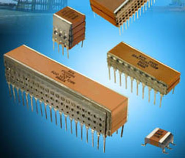
Fig. 2: AVX stacked ceramic capacitors.
Other downhole applications that use 200°C stacked MLCCs include start-and-run capacitors in ac induction motors. These motors power the rotary drill tables that provide rotational force to the drills, high-pressure mud pumps, operation of the draw-works, compressors for riser tensioning, and conveyors that transfer drilled solids, equipment, pipes, and supplies on an offshore oil platform.
Advertisement
Learn more about AVX


