By JOHN BAZINET,
Staff Scientist, Power Products
STEVE KNOTH,
Senior Product Marketing Engineer, Power Products
SAM NORK,
Director, Boston Design Center, Power Products
Linear Technology
www.linear.com
As the cost to produce supercapacitors (SCAPs, or ultracapacitors) continues to decline, they are carving out a niche in the marketplace between conventional capacitors and batteries. And, although supercaps require some “care and feeding,” they are replacing batteries in data storage applications requiring high current/short duration backup power. Furthermore, they are also finding use in a variety of high peak power and portable applications in need of high current bursts or momentary battery backup. Compared to batteries, supercaps provide higher peak power bursts in smaller form factors and feature longer charge cycle life over a wider operating temperature range (see Fig. 1 ). Compared to standard ceramic, tantalum or electrolytic capacitors, supercaps offer higher energy density and higher capacitance in a similar form factor and weight (see Table 1 ). Moreover, supercap lifetime is maximized by reducing the capacitor’s top-off voltage and avoiding high temperatures (>50°C).
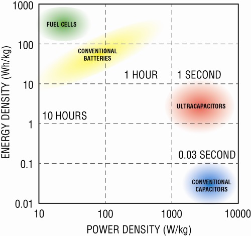
Fig. 1: Storage element energy density vs. power density
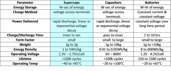
Table 1. Supercapacitor comparison with capacitors and batteries
Summary of supercaps vs. batteries :
• Batteries :
• Good energy density
• OK power density
• High ESR at cold temperatures
• Supercaps :
• OK energy density
• Good power density
• Low ESR – even at cold temperatures (~2x increase at –20°C vs. 25°C)
• Supercap Limitations :
• Limited to 2.5V or 2.75V max
• BAT insertion inrush current too high
• No reverse current protection in hold-up applications
• Series Supercap Benefits :
• Allow for better energy utilization
• E = 1/2 CV2
• Simplify “dying gasp” / backup circuits
• Step-Down vs. Boost for 3.3V backup
• Good for high power backup, industrial temperatures
• Potential Problems for Series Supercaps :
• SCAPs can have mismatched capacitances
• SCAP leakage mismatches can cause overvoltage over time – cells need continuous balancing
• SCAP capacitance and ESR degrades over time and not always at the same rate
• SCAP degradation accelerated by overvoltage and high temperatures
Supercap design challenges
Supercaps have advantages; however, when faced with charging energy storage devices in series, the end product designer may be faced with such problems as cell balancing, cell overvoltage damage while charging, excessive current draw and a large footprint/solution when space is critical.
Cell balancing in series-connected capacitors ensures that the voltage across each cell is approximately equal; a lack of cell balancing in a supercapacitor may lead to overvoltage damage. External circuitry with one balancing resistor per cell is one solution to this problem. The balancing resistor value will depend on the supercap operating temperature and charge/discharge profile. In order to limit the impact of the current drain due to balancing resistors on supercap energy storage, designers can alternatively use a very low current active balancing circuit. Another source of cell mismatch is differences in leakage current. Leakage current in the capacitor cells starts off quite high and then decays to lower values over time. But if the leakage is mismatched between series cells, the cells may become over-voltaged upon recharge unless the designer swamps out the leakage with the balance resistors. However, balancing resistors burden the application circuit with unwanted components and load current.
Supercap charger IC design challenges
Some of the tougher issues a designer must consider in the beginning of a supercapacitor charging project are the needs for:
• High efficiency and high charge current. A high efficiency, high current buck-boost supercapacitor charger/balancer includes all the features and functionality required to exploit the benefits of super capacitors. Discrete solutions, while possible, are complicated, larger, lower efficiency and less accurate.
• High accuracy and load sharing capability. Input current limit with ±2% accuracy and input load sharing enables multiple loads to share the full capability of same power source with minimal derating/margin. This functionality is impractical to achieve with a discrete solution.
• Active balancing. Most supercapacitor systems utilize dissipative (resistor) balancing. Active balancing efficiently shuttles charge between the capacitors, eliminating the power losses and required subsequent recharge cycles with dissipative methods.
New solutions for supercapacitor backup systems
A buck-boost IC supercapacitor charging solution that solves the problems already outlined needs to possess all of the following attributes:
• Flexibility – it must operate efficiently in step-up or step-down modes
• Can perform active charge balancing with programmable maximum capacitor voltage
• Provide high charge current
• Have accurate programmable average input current limit
• Be a small, low profile solution footprint
• Possess advanced packaging for improved thermal performance and space efficiency
The LTC3128 buck-boost supercap charger with active balancing
The LTC3128 is a high efficiency, input current-limited buck-boost supercapacitor charger with active charge balancing for 1- or 2-series supercapacitors. It features an average input current limit that can be programmed up to 3A with ±2% accuracy, preventing power source overload while minimizing capacitor recharge time. Highly efficient active charge balancing eliminates dissipative external ballast resistors, ensuring balanced operation and charging even with mismatched capacitors, and less frequent recharge cycles. A programmable maximum capacitor voltage clamp actively monitors and enforces the voltage across each capacitor in the series stack, ensuring reliable operation as capacitors age and develop mismatched capacities. The low noise buck-boost topology allows the output supercapacitor to be charged whether it is above or below the input. The low-RDS(ON) , low gate charge synchronous switches provide high efficiency conversion to minimize the charging time of storage elements. This combination of features makes the LTC3128 suitable for safely charging and protecting large capacitors in backup power applications. See Fig. 2 for a typical backup application circuit.
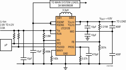
Fig. 2: LTC3128 Typical Backup Application Circuit
The LTC3128’s input current limit and maximum capacitor voltage are each programmed using a single resistor. Average input current is accurately controlled over a 0.5 to 3 A programming range, and the individual maximum capacitor voltage can be set from 1.6 to 3.0V. Other features of the LTC3128 include Efficient Charging
The LTC3128 uses fixed frequency, average input current PWM control when charging the output capacitor(s). A proprietary switching algorithm allows the charger to switch between buck and boost modes without discontinuity in inductor current or loop characteristics.
The ability to effectively and efficiently step-up or step-down supercapacitor charging while protecting and balancing the cells, greatly simplifies what was historically a very difficult design task. The LTC3128 is an average input current controlled buck-boost dc/dc supercapacitor charger, usinga proprietary switching algorithm that enables the output to be regulated above, below, or equal to the input voltage. For more information, go to www.linear.com/products/supercapacitor_chargers
Advertisement
Learn more about Linear Technology


