By JASON P LEE, Global Product Manager,
Eaton,
With the promise of long-life and durability as energy storage devices, supercapacitors have garnered the attention of electronic designers as system integration rates climb rapidly. However, designers need to take a few initial steps to properly choose components to ensure the longest life the application. The selected parameters described here will suggest a path to the optimal selection process.
Costs of supercapacitors are coming down rapidly with greater adoption. With proper implementation, they provide a cost-effective power solution over the lifetime of a product. Additionally, they require virtually no maintenance, minimal monitoring and carry none of the hazards of batteries.
Designers implementing supercapacitor energy storage need some basic system requirements to begin sizing the appropriate component. This will begin a selection process involving key considerations and calculations that will lead to faster circuit design integration. The effects of temperature and equivalent series resistance (ESR) will be introduced and some preliminary equations for sizing will be provided.
The considerations and calculations provided below are initial starting points. To select the right supercapacitor for an application, designers will need to know these four basic requirements:
• Normal operating voltage;
• Minimum operating voltage or cutoff voltage for the device;
• Current or power;
• Duration of pulse or hold-up time.
Additional information regarding ambient temperature profiles will aid in the final selection process. Temperature and voltage are the key factors affecting lifetime. Operating temperature range and life will enable a designer to anticipate changes in the capacitor parameters over time and ensure sufficient design margin by adjusting voltage.
Additional evaluation criteria:
• DC resistance. This is a critical parameter as it affects the effective operating voltage drop and operating temperature rise due to current;
• Life/aging due to temperature and time;
• Initial tolerance;
• Balancing circuit and cell leakage currents.
These criteria help to account for real life conditions and aid in selecting a component optimized for a particular application.
Voltage Drop
During discharge there is an initial voltage drop due to the equivalent series resistance. This is followed by a voltage drop due to the reduction in energy stored. These are known as resistive and capacitive voltage drops and it’s important to consider both. The capacitive component represents the voltage change due to the real energy delivered by the supercapacitor. The resistive component represents the voltage change due to the ESR.
Temperature and voltage directly affect the life or aging of supercapacitors. Life extends approximately 2.2 times for every 10°C; Life extends 2.2 times for every 0.2 V reduction, and the Arrhenius plots shown below helps to visualize the temperature and voltage effects. (Note that these values are approximations and vary by manufacturer, design and voltage.)
Fig. 1: When sizing supercapacitors, voltage drops due to initial current pulse (ESR) and l Life/aging due to time, voltage, and temperature, as shown in the Arrhenius graph above.
Temperature also has an effect on the operation of supercapacitors. The ESR increases at lower temperatures. Higher ESR will increase the voltage drop and should be accounted for in an optimum design. Capacitance is also affected by temperature, although to a much less extent. Capacitance decreases as temperature decreases and increases as the temperature increases. The initial capacitance tolerance is the possible variation or change of capacitance a capacitor may have from lot to lot and should be considered during the sizing process.
Series or Parallel?
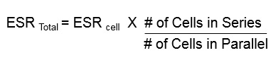
Supercapacitors can be designed in series or in parallel to achieve various voltage and energy levels. Placing capacitors in series will increase the voltage rating by adding the voltage rating of each supercapacitor in series. So, two 2.5 V caps in series will achieve a 5 V rating. However, when placing capacitors in series, the capacitance will decrease and ESR will increase. So, two 5 Farad (F) supercapacitors in series will equate to 2.5 F with an ESR that is two times the listed rating.
Energy storage can be increased by placing capacitors in parallel. Capacitance increases by adding the capacitance rating of a cap in parallel. If two 5 F caps in parallel would equal 10 F, the ESR will decrease and the voltage rating will not change.
Useful Equations
There are a few basic equations that are used in the initial stages for selecting and sizing. In the examples shown below, the first solves the initial voltage drop due to ESR, the second solves the initial voltage drop due to capacitance. The third combines equation one and two and will solve for the total voltage drop.
Initial drop in voltage is due to the (ESR):
• The amount of drop is a function of the ESR and discharge current as indicated by the equation below:
Equation 1 : dVESR = Iload * ESR
• The capacitor will discharge according to its capacitance:
Equation 2 : dVcap = Iload * td/C
• By placing these two equations together the total voltage drop:
Equation 3 : dVTotal = Iload * td/C + Iload * ESR
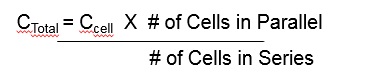
• Equation four solves for the total capacitance value.
Equation 4 :
- Equation five solves for the total ESR
- Equation 5 :
 After determining the basic formulas and parameters needed, some real world examples can help a designer work through these calculations. The first example uses a constant current application. To start the designer will initially ignore the ESR effect on the voltage drop to get an estimate on the capacitance and then use Equation 3 to verify if the size picked will work with the ESR effect. Equation 6 is created by removing the ESR portion and rearranging the equation to solve for capacitance.
Equation 6 : C = Iload * td/dVTotal
Using the formula C = Iload * td/dVTotal , the result is C= 4*5/(16-9) = 2.86 F. This is the total capacitance at 16 V. Since supercapacitor cells are typically rated at 2.5 or 2.7 V then, divide the operating voltage VWV by 2.7 and round up, 16/2.7 = 5.9, this means the designer will need 6 cells in series. Since capacitance divides with cells in series, the designer will need to calculate the capacitance needed per cell. Using equation 7 to solve for Ccell , Ccell = Ctotal * # in Series = 2.86 * 6=17.16 F, the designer will need approximately 17.16 F minimum per supercapacitor cell.
Equation 7 : Ccell = Ctotal * number in series
With a product selection chart, the closest size available is 25 F. Now the designer will use equation 3 and use the 25 F and ESR value 0.027 to determine the voltage drop.
 Fig. 2: The product selection chart based on results from the equations
 For example:
• Taking the capacitance and ESR value of this cell and plug it into Equation 3 to Check on Voltage drop.
• dVTotal = (4*5/ (25/6)) + (4* (.027*6)) = 4.8 + 0.65 = 5.45
• The above voltage drop is less than the 7 V (Vop-Vmin) allowed. Therefore 6 cells of 25 F in series will meet the initial requirements.The formulas and criteria outlined above serve as a starting point to help system designers better understand how to size a supercapacitor. Other aspects that should be considered calculating for end-of-life and for constant power applications.
Supercapacitor calculators available for download make this process easier and the one that Eaton provides is just one example. Visit www.eaton.com/elx and click the “Supercapacitor Calculator” link to find out more.
Advertisement
Learn more about Eaton, Power Quality


