BY MIKE ROACH, Technical Sales Manager
AEM Components
www.aemcomponents.com
Automotive applications for electronics are subjected to among the harshest of environments — wide temperature variations, shock and vibration, and exposure to humidity, water, and salt. Traditionally, blade-type automotive fuses, located under the dashboard in a fuse box, provided the necessary fault protection. But as cars get “smart” and “connected,” more and more embedded and distributed electronics have required pc board-mounted circuit protection. And with the rapid emergence of electric (EV) and hybrid electric (HEV) vehicles — most with high-energy lithium battery systems — the demand for reliable circuit protection devices to protect against catastrophic failures is critical. These applications have placed emphasis on improving surface-mount fuse technology.
This article describes the common types of one-time, surface-mount fuses and compares alternative fuse structures for each type. It presents the results of comparison tests simulating real-world application scenarios to demonstrate the dramatically better performance offered by the latest generation of surface-mount fuses.
The need for surface-mount fuses
Historically, it is typically an industry’s need for technology advances that ultimately drives adoption in a wide range of applications. For example, brighter, more efficient, and lighter displays — first developed by the television industry — are now an integral part of consumer, commercial, industrial, military, and aerospace applications. In a similar way, it would appear that the demands of the automotive industry are driving advances in circuit protection technology.
Resettable devices are the ideal choice in which overcurrent conditions are the result of a transitory fault condition. But in many applications, particularly where fault currents can result in serious damage to other circuits or systems, the venerable fuse is still the best choice for protection. While traditional clip-mounted glass-tube fuses are found in a host of applications and blade-type fuses are ubiquitous in automotive applications, the move toward smaller, distributed, and embedded electronic functionality has elevated the demand for high-performance, space-saving surface-mount fuses. In a similar manner as chip inductors and multi-layer ceramic capacitors (MLCCs), surface-mount fuses are packaged in a variety of EIA standard sizes determined by the technology uses and the rating.
While others exist, this article focuses on common surface-mount fuse types: solid-body, or chip, fuses and wire-in-air fuses.
Solid-body (chip) fuses
Solid-body, or chip, fuses are used in a very wide range of space-constrained applications, including portable electronics, entertainment systems, disk drives, and many others. Current ratings typically range from as low as 125 mA to several amperes. Devices are offered in both slow-blow and fast-acting configurations.
The two most common structures for solid-body fuses are the multi-layer ceramic type and printed-circuit style. The ceramic fuse has a co-fired monolithic structure with up to four layers of fusible material embedded in the structure. In the printed circuit structure, the device is mainly comprised of the epoxy substrate and glass fiber (FR4) structure. The fuse element is bonded to the surface of the pc board and coated with a protective polymer.
While the printed-circuit style is most common, the ceramic type offers several distinct advantages. Because of its monolithic structure, it is capable of higher current ratings in a smaller package, has a wider operating temperature, and has stable operating characteristics in extreme conditions. Additionally, the structure is less susceptible to mechanical damage.
A new advancement in ceramic fuse technology is the SolidMatrix ceramic fuse. This solid-body ceramic fuse’s patented, multi-layer construction provides excellent mechanical and thermal stability over a wide temperature range (–55°C to 150°C).
Fig. 1 shows a how a SolidMatrix ceramic fuse and a conventional printed-circuit-type fuse might behave when subjected to an overcurrent fault condition. The fuse element of the conventional printed-circuit-board-type fuse on the right opened as intended, but the high overcurrent fault condition led to surface melting, cracking, and compromised mechanical integrity. As a result, arcing and surface damage are very apparent in the image on the right.
The SolidMatrix ceramic fuse, as shown in the left-hand image in Fig. 1 , fared significantly better. The proprietary construction of this device allows for the metal fusing elements to be defused into the ceramic; plus, their central location ensures that the energy is contained within the body. As a result, mechanical integrity is maintained and there is no external change in the device’s appearance.
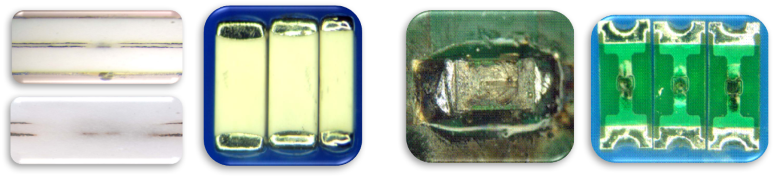
Fig. 1: Monolithic structure of a SolidMatrix ceramic fuse (left) absorbs fault current and shows no external damage — compared to the visible damage of the conventional printed-circuit-type chip fuse (right).
Wire-in-air fuses
Wire-in-air fuses are typically found in higher-operating-current applications in which fast-acting and superior arc suppression are required. Applications include battery chargers, battery packs, and circuits subject to very high fault currents and higher voltages. The common construction for this type of fuse has the fusible wire element housed inside a ceramic tube and connected to the endcaps with solder beads.
There are several disadvantages associated with conventional wire-in-air fuses. Endcap detachment is a common failure mode in the conventional construction. There is also a lack of uniformity in performance due to the variability in the placement of the wire element inside the ceramic tube. Additionally, under worst-case, high-current-stress conditions, the solder in the ceramic tube can vaporize and build up pressure to the point where the fuse explodes. If this occurs, solder is redeposited across the trace, which can result in a secondary conductive path with potentially serious consequences.
In comparison, the fuse element of advanced AirMatrix wire-in-air fuses uses a proprietary, hermetically sealed wire-in-air structure that ensures consistent electrical performance. The AirMatrix’s fuse element is uniformly straight across the cavity and externally bonded to the endcap. Unlike the conventional square nano-type fuse, with its ceramic body and solder connect design, the AirMatrix fuse uses a fiberglass-enforced body and solderless direct connect construction.
Fig. 2 shows two conventional wire-in-air fuses subjected to an EV short-circuit condition. Sample A at 250 V/250 A (left image) and Sample B at 450 V/450 A exhibited significant damage to the fuse and collateral damage to the surrounding circuitry. In the waveforms, the current flow (yellow trace) through the fuses each displays secondary current flow that ultimately resulted in pc board damage.

Fig. 2: Damage resulting from two conventional wire-in-air fuses subjected to extreme overload conditions — simulating a catastrophic EV battery short-circuit.
High-speed video at 5 frames/s shows conventional wire-in-air fuses subjected to an EV short circuit condition. Video of Figure 2A results of the 250V/250A Pulse Test,
and video of Figure 2B results of the 450 V/450 A Pulse test. Both exhibited significant damage to the fuse and collateral damage to the surrounding circuitry.
When subjected to the same EV battery short-circuit as the square nanotube fuses, the AirMatrix fuse’s advanced construction withstood 450-V/450 A conditions without experiencing any external damage (see Fig. 3 ). Note how in the waveforms, the current flow (yellow trace) through the AirMatrix fuse drops to zero. The voltage (green trace) shows an open circuit for the AirMatrix fuse with no secondary conduction.
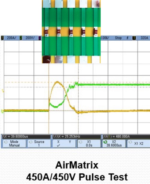
Fig. 3: AirMatrix fuse sustains no damage after being subjected to extreme overload conditions — simulating a catastrophic EV battery short-circuit.
Meeting automotive standards
Automotive applications engineers need to qualify their devices for the AEC-Q200 automotive standard. As demonstrated by reliability testing, new structures being utilized by SolidMatrix multi-layer ceramic chip fuse and the AirMatrix wire-in-air fuse offer significant advantages over typical fuse approaches. These fuses are manufactured in a TS16949-certified facility and are specifically designed for reliable operation in high-stress automotive applications.
Advertisement


