Switching frequency and efficiency: A complex relationship
The effects of switching frequency on power loss in a flyback converter can be assigned switching losses in the power MOSFET and losses in the core and windings of the power transformer
BY ANDREW SMITH
Senior Product Marketing Manager
Power Integrations
www.powerint.com
Power supply designers can increase efficiency while moving to a higher switching frequency. To prove this, engineers at Power Integrations tested comparable flyback designs running at 66 and 132 kHz. They examined losses associated with different aspects of the design and showed that, in some cases, the widely-held assumption about high switching frequencies — the higher the switching frequency of a power supply, the lower its efficiency — is wrong. This article will explain why this assumption does not hold true and why engineers can even increase efficiency by moving to a higher frequency.
Switching frequency does affect power loss in a switching power supply. The effects of switching frequency on power loss in a flyback converter can be assigned to basic two types: switching losses in the power MOSFET and losses in the core and windings of the power transformer. In this article we will focus on the transformer effects of changes to switching frequency. Transformer losses can be divided into core loss — the energy used in magnetizing the core, and the conduction loss associated with passing current through the windings of the transformer. In the latter case, wire size, path length and winding density all have a role to play.
Factors driving core loss
When you double the switching frequency in a design, you halve your flux density for a given number of turns in the transformer. So the designer can reduce the core size or reduce the number of turns or proportionally reduce both. This relationship accounts for one of the primary motivations for moving to higher frequency designs; they allow the use of smaller magnetic components.
Smaller cores can more easily tolerate a higher peak flux density at higher switching frequencies than larger cores. Why? Because core loss is proportional to volume but cooling is proportional to the core’s radiating surface area.
The following calculation illustrates the relationships.
For a flyback topology:
Pcore = Pv * Ve/2
Where Ve = core volume (mm3 )
Pv = specific power loss (kW/m3 ) and can be estimated from core manufacturers data curves (such as the typical curve shown below in Fig. 1 ).
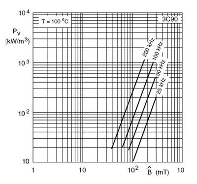
Fig. 1: Typical specific power loss curves for different switching frequencies and flux densities
Using the values in Table 1 , the core loss of a PQ2620 core with a flux density of mT at 50 and 100 kHz (assuming 3C90 material at T = 100C) can be calculated.
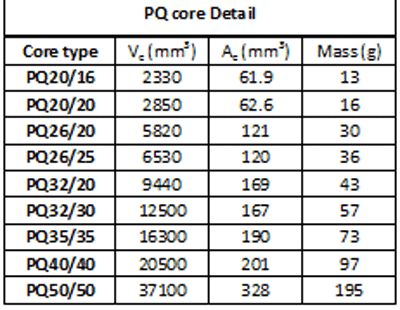
Table 1: PQ core data
50 kHz: Pcore PQ2620 = 30 kW/m3 * 5820 mm3 /2 = 0.087 W
100 kHz: Pcore PQ2630 = 70 kW/m3 * 5820 mm3 /2 = 0.204 W
The core switching at the higher frequency clearly shows higher loss.
Changing core sizes to optimize design for different switching frequencies:
Pcore PQ3220 = 30 kW/m3 * 9440 mm3/2 = 0.147 W @ 50 kHz
Pcore PQ2620 = 70 kW/m3 * 5820 mm3 /2 = 0.204 W @ 100 kHz
Pcore PQ3220 = 70 kW/m3 * 9440 mm3 /2 = 0.330 W @ 100 kHz
As conventional wisdom would suggest, the smaller core switching at the higher frequency exhibits a higher loss.
Table 2 highlights this distinction. Columns 2 and 3 illustrate what happens when the flux density doubles. In the first case (Pcore calculated at 50 kHz and 100 mT flux density), the increase in core loss between the smaller PQ2620 core and the larger PQ3220 core is relatively modest, while the effect of increasing flux density is dramatic.

Table 2: Core losses.
In most applications where designers consider moving to a higher switching frequency, they do so because design space is limited and they need to use smaller magnetic components. To minimize the size of the core, they push peak flux density as high as possible. Moving to a higher switching frequency, however, can also be viewed as an opportunity for the designer to use fewer turns, in order to reduce flux density and therefore help efficiency.
Copper losses in smaller core sizes
Faraday’s Law describes the relationship between flux density, the number of turns and the required frequency for a transformer design. Flux density is inversely proportional to the number of turns, core area and switching frequency.
Bmax = E * 10-8 / (k * N * Ae * fsw)
Copper Loss
Increasing switching frequency can also reduce copper loss. Higher frequency means fewer turns, reducing the winding length and allowing a larger gauge wire to be used in a given winding space (window). The lower number of turns drives down dc-resistance (Rdc). One cause of increased resistance is the skin effect: As frequency increases, eddy current effects in the conductors tend to force current to flow in the surface of the wire.
The other cause of ac-winding resistance is the proximity effect in which the charged carriers (electrons) in adjacent wires tend to repel each other, reducing current flow in the surface area near adjacent windings. Proximity effect can be controlled by reducing the number of wire layers and increasing wire size, but this must be balanced with skin effect. The impact of skin effect (Rac) can be minimized by carefully sizing the wire and using multiple strands which keep Rac /Rdc close to 1 (a value of 1 would describe a system where the proximity effects and skin effects have been eliminated). Rac does not depart radically from Rdc for frequencies below 150 kHz provided care is taken with respect to the parameters described above.
By managing the construction of the transformer to take advantage of fewer turns and shorter path lengths, winding losses can complement the reduction in power loss associated with smaller cores and/or lower flux density, or compensate for the magnetization losses of a larger core being driven with fewer turns. By reallocating the winding space liberated by using fewer primary turns to increased secondary (high current) winding thickness, significant increase in efficiency can be achieved.
The effect can be seen in Fig. 2 by comparing thermal scans for an RM10 in 132- and 66-kHz designs. Here we see that the core temperature of the 132-kHz design was 12.2C lower than the 66-kHz design. At the same time, the wire temperature in the higher frequency design was 15C cooler. In this design the increased winding window (thicker gauge wire) and fewer turns effectively compensated for the increased core magnetization losses (reduced by the lower flux density) of the higher frequency RM10 design.
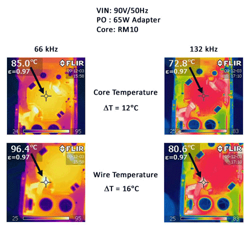
Fig. 2: Transformer thermal scan.
The higher switching frequency of the 132-kHz design used the same size core with fewer turns. That advantage reduced peak flux density as well as copper loss. To keep peak flux density low in the 66-kHz design, the engineer doubled the number of turns, which required a larger number of turns increasing copper loss.
MOSFET switching losses
The role of the primary parasitic capacitance of the transformer will have a direct effect on switching losses, as do the contributions of the MOSFET parasitic capacitances (CISS and COSS). For now, assume that with the correct switch design, using MOSFET technology optimized for high frequency switching, the switching loss change will be relatively small compared to the improvements outlined in the transformer design considerations.
Radiated and conducted EMI (see Fig. 3 ) did not present unique problems for the 132-kHz design. In fact, as the graphic below indicates, the use of an optimized layout and carefully constructed transformer design actually offered better EMI performance than the 66-kHz design.
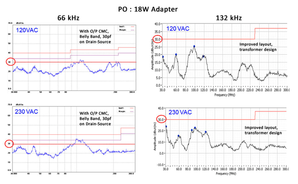
Fig. 3: Conducted and radiated EMI comparison between 66- and 132-kHz designs.
Design examples
Figure 4 and Table 3 compare efficiency and critical parameters for three different examples of a 65-W adapter design using a single RM10 core. One example operates at 132 kHz (blue), while the other two switch at 66 kHz. The first 66-kHz version matches the number of turns of the 132-kHz version (pink). However, since flux density has a larger impact on core loss than frequency (and the flux density in the 66-kHz version is almost double that of the 132-kHz option); the higher frequency solution offers significantly better efficiency across most of the load-range.
The second 66-kHz design demonstrates what happens when designers attempt to keep switching frequency low and reduce flux density (blue). This design strategy required a higher number of turns which drove up copper loss and, again, resulted in a lower efficiency solution compared to the 132-kHz option.
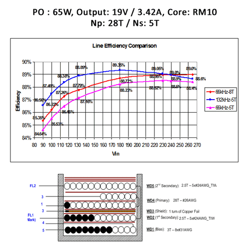
Fig. 4: Design example.

Table 3: Efficiency comparison of critical parameters for 65-W adapter
The experiment demonstrated that, in some cases, conventional wisdom about the relationship between switching frequency and efficiency is wrong. Power supply designers can drive down their costs with higher frequency designs that enable them to use smaller, cheaper cores and less copper or make better utilization of existing cores. Smaller cores reduce core loss and fewer turns reduce copper loss. In the end, the higher frequency design may be the most efficient solution.
■
Advertisement
Learn more about Power Integrations


