As lighting topologies have advanced, backlighting technologies have evolved to keep pace. At one time, cold-cathode fluorescent lamps (CCFLs) were the dominant technology for backlighting active-matrix thin-film transistor (TFT) LCDs and were powered by dc/ac inverters.
Now, LED backlights have taken over. Their advantages over CCFL have been well documented — higher brightness, longer lifetime, lower power consumption, and no mercury, to name a few. The rising prominence of LED backlights (see Fig. 1 ), usually in the form of rails, strings or LED arrays, has presented many manufacturers and users of display power supplies with a number of options.

Fig. 1: CCFL tube BLUs (top) are rapidly giving way to LED strings or rails (bottom) for LCD backlighting.
There are currently four options for backlighting a display: (1) continue to use CCFLs with dc/ac inverters for as long as parts are available, (2) make an easy switch to an LED driver using a number of options currently on the market such as kits and drop-ins, (3) choose an LED driver, standard or newly designed, for an LED display that does not come with an onboard driver, and (4) for the display that has an onboard driver, it is possible to use the system’s existing input power signals and convert the analog dimming signal used for the inverter into a PWM signal for the LED driver.
CCFL still hanging on
CCFLs are not entirely dead yet, and they are still an option for certain legacy applications (for example, medical and point-of-sale) where a re-design for LED backlighting is not yet necessary or economical. And, although many CCFL and inverter manufacturers are abandoning this technology, there are a few that continue to support the CCFL industry so that customers have that option for as long as they need it. CCFLs are not the future but, at present, a demand remains and a few manufacturers — ERG included — are still selling them to support customers who continue to use CCFL.
The majority of LCD users, however, are switching to LED backlights. The optimum scenario here is to make the transition from CCFL to LED as quick and easy as possible while getting the optimum performance from the LED BLUs (backlight units).
Making a quick switch to LED
If you are sourcing a driver for an LED backlit LCD, you have a few options that can make the switch surprisingly fast and easy.
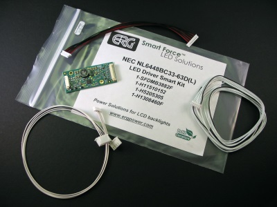
One option is a development kit available (see Fig. 2 ) for OEM LED-backlit LCDs that includes everything necessary to get the panel, backlight and driver fully operational. Each kit is designed for a specific OEM LCD and includes the appropriate LED driver card, a flying lead input harness, a controller-to-driver plug-and-play input harness, and a direct mate LED driver-to-LCD interconnect wiring harness (where applicable).

Fig. 2: Development kits are available forLED-backlit panels in popular industrial sizes from AOU, NEC, Sharp, Kyocera and other major LCD OEMs.
For CCFL designs already in the field, it’s possible to swap an LED rail for the CCFL lamp, or tube. LED rails are available on a long, narrow PC board that fits into a metal channel or “rail” that is similar in form factor to the channel in which CCFLs are commonly fitted. These are available as a drop-in replacement (see Fig. 3 ) for CCFL rails for a number of OEM LCDs and, used in conjunction with LED driver boards that replace the dc/ac inverters, they can provide the simpler and less costly option of replacing the lamps and power sources in an existing LCD rather than re-designing the whole system.
For example, if you need a driver that won't require hardware redesign, drop-in replacements are available that offer the same mechanical footprint as dc/ac inverters in the field (ERG's and those of other inverter manufacturers) with pin-for-pin compatibility. This allows for a fast, easy upgrade to LED backlighting without re-designing or re-tooling the mounting hardware.

Fig. 3. These drop-in replacement LED driver boards have the same length and width dimensions as their DC-AC inverter counterparts as well as matching input connects and mounting holes.
Selecting or designing an LED driver
There are many standard LED drivers available on the market today. However, LED backlights create new challenges for the power supply driving the BLU, challenges that cannot be met by the many single-chip ICs currently available. Getting optimum performance from LED BLUs requires a full-function power supply, ideally from a company that has experience in power solutions for LCD backlights and understands such issues as:
• What voltage does the device need to accurately regulate current? Is there enough voltage across the device to light the LED string and provide proper current regulation?
• Is the power supply designed to account for this voltage change and can it light across the entire normal operating range of temperatures, with no time or expense devoted to designing a boost circuit?
• What about the LED BLU itself? Does it address the challenge of keeping the LEDs cool? Does it conduct heat from the LEDs with enough efficiency to keep the junction temperature at or below the recommended operating temperature, which is critical to preventing overheating and ensuring cool, high-brightness, long-life operation of the LED BLU?
An experienced LED driver manufacturer can offer a wide range of standard and custom product that provides high-efficiency power to LED backlights.
Use the system’s existing signals
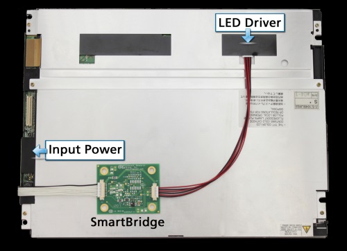
Another option is to integrate an LED display into an existing design by providing interconnectivity from the existing controller or power supply to the LCD backlight driver. If the current LCD is going end-of-life and the recommended replacement LCD has an LED backlight and a built-in driver, there is an option that can make the LCD upgrade as seamless as possible. The module shown in Fig. 4 uses the system’s existing input power signals and converts the analog dimming signal used for the inverter into a PWM signal for the LED driver. In this way, the system’s existing signals are used, powering the LED backlight driver without additional modifications.

Fig 4. This “Smart Bridge” module uses existing input power signals and converts the analog dimming signal used for the inverter into a PWM signal for the LED driver.
Whether you are trying to support your current CCFL design as long as possible or planning to upgrade to the efficiency and economy of LEDs, there are a multitude of options available if you know where to look for them.
Related Products: LEDs and LED Lighting
Advertisement
Learn more about Endicott Research Group


