The production process of Digital Micromirror Devices (DMDs) produces remarkably consistent results, especially considering the very small dimensions of an individual pixel. The DMD production tilt angle specification is 12° with only ±1° variance. This article looks at the challenges facing designers of High Demagnification Systems using DMDs.
High Demagnification Systems
Background
Traditional Projection Systems
In traditional consumer projection applications, a DMD-based projection system is designed for a 12° half-angle cone of input (illumination) centered on -24° from normal. Since the DMD is a reflective device with an on-state tilt angle of 12°, the resulting reflected output light is an equal size, 12° half-angle cone, centered on the DMD normal [See Fig. 1]. This configuration is very tolerant of tilt angle variations across a single DMD and from device to device.
In these typical projection systems, the lowest F number that can be realized without overlapping the light cones is F/2.4. 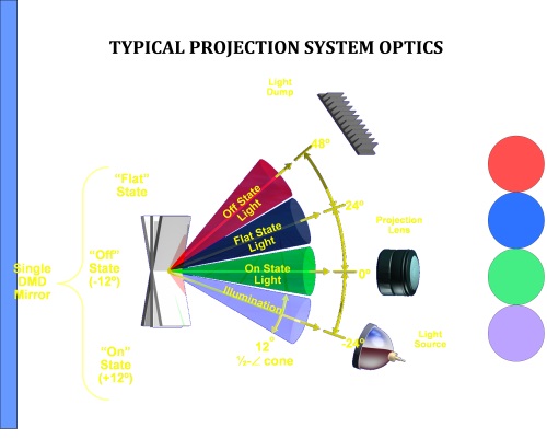
Fig. 1: DMD Input and Output Light Cones.
Small Aperture Systems
Many industrial customers contemplate systems that are designed with much smaller input cones and output cones [see Fig. 2]. Examples are direct imaging lithography systems, LCD panel defect-correction tools, and very small scale 3D measurement systems.
These design considerations are often driven by space constraints, depth of field requirements and the desire to reduce the cost of the optical elements (less glass). One tradeoff to this design approach is very low tolerance to DMD production tilt angle variations.
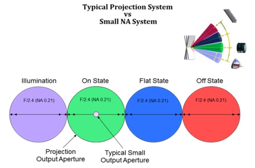
Fig. 2: Relative Projection System Cone Diameters versus Small Output Aperture
The production process of the DMD produces extremely consistent results. However, there is some variation across a given die of the on (& off) tilt angle and variations from die to die. These are both accounted for in the traditional DMD tilt specification of 12° ±1°.
If a system is designed that contemplates significantly less than ±1° tilt variation, the chances are great that brightness variations across the image of DMD will be observed. This is due to tilt variations.
To understand why this occurs when small input and output cones of light are employed, look at the effect of tilt variation on a system that employs cones considerably smaller than the tilt variation.
The input cone is not impacted by the state or tilt of the pixel. It remains centered on -24° from the DMD normal. However, the reflection of the illumination cone is dependent on the tilt angle. In fact, the angle of the center of the reflected illumination cone moves at two times the variation in tilt.
Envision an illumination cone with a half angle of 1.5°. If the DMD pixel tilt is exactly 12° then the result is a reflected output cone centered on the DMD normal with a half angle of 1.5°. If the system is designed with an output aperture that only accepts this cone centered on the normal ±1.5°, what will happen if the pixel actually has a tilt of 12.2°? The center of the output cone will move 0.4° away from the cone and part of the output cone will not be captured by the aperture [see Fig. 3].
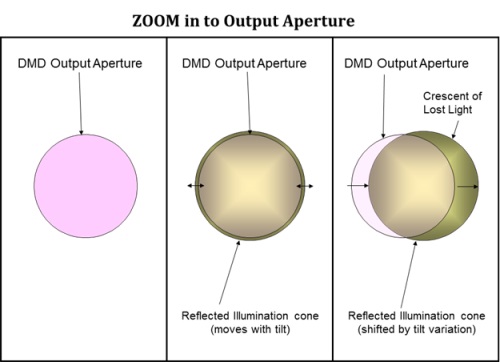
Fig. 3: Effect of Tilt Variation on Reflected Illumination Cone Relative to Output Aperture
Solution
It is desirable to develop a system that is optically consistent over the DMD tilt angle variation specification.
Below are two potential approaches to designing such systems:
Overfill the output aperture with uniform illumination.
Enlarge the input cone sufficiently so that variations in the DMD tilt angle result in the same amount of light being gathered by the output aperture.
Reduce the output aperture cone sufficiently so that variations in the DMD tilt angle result in the same amount of light being gathered by the output aperture.
A combination of both.
Underfill the output aperture
Enlarge the output aperture sufficiently so that variations in the DMD tilt angle result in the reflected output cone remaining completely within the output aperture.
Reduce the input cone sufficiently so that variations in the DMD tilt angle result in the reflected output cone remaining completely within the output aperture.
A combination of both
Each of these approaches has advantages and disadvantages. Which one is employed should be based the needs of the particular system and is left to the system designer to decide
Option 1 – Overfill the output aperture with uniform illumination
In this solution the illumination is expanded to overfill the output aperture by 2° in the illumination cone’s half angle. Then as the illumination reflection moves with variation in tilt angle the output aperture remains within the reflected illumination bundle. If the illumination field is uniform as the reflected cone moves with tilt angle the light captured by the output aperture remains constant.
If the tilt varies by ± 1° the reflection of the illumination cone moves through ± 2°. This means that the reflection of the illumination cone completely covers the output aperture for all production variations in tilt angle.
There are three ways to accomplish this:
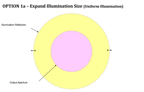
Fig. 4: Option1a – Enlarge the input cone sufficiently so that variations in tilt result in the output aperture remaining within the reflected illumination cone
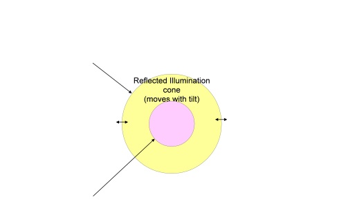
Fig. 5: Option 1b – Reduce the output aperture sufficiently so that variations in tilt result in the output aperture remaining within the reflected illumination cone
For option 1b if the illumination bundle is already small (1c – (Combination of 1a & 1b.) Enlarge the input cone and reduce the output aperture sufficiently so that variations in tilt result in the output aperture remaining within the reflected illumination cone.
The caveat for this method is that a significant amount of light is thrown away. In applications where every photon is precious, this option may not be ideal. Moreover, since extra light energy is necessary to fill the larger area, more heat will be imparted to the DMD requiring additional capacity in the DMD thermal solution.
Option 2 – Underfill the output aperture .
In this solution the illumination underfills the output aperture (by 2° in the cone’s ½ angle). Then as the illumination reflection moves with variation in tilt angle the reflected illumination bundle remains with the output aperture. Illumination uniformity is not critical to this implementation since the all of the light is collected somewhere in the output aperture.
As the tilt varies by ± 1° the reflection of the illumination cone moves through ± 2°. This means that the reflected illumination bundle is always within the output aperture for all production variations in tilt angle.
Again there are three methods to achieve this:
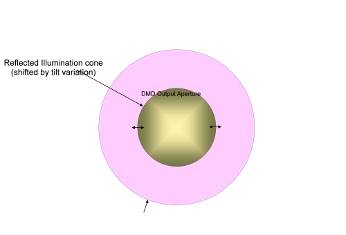
Fig. 6: Option 2a: Enlarge the output aperture sufficiently so that variations in tilt result in the reflected output cone remaining completely within the output aperture
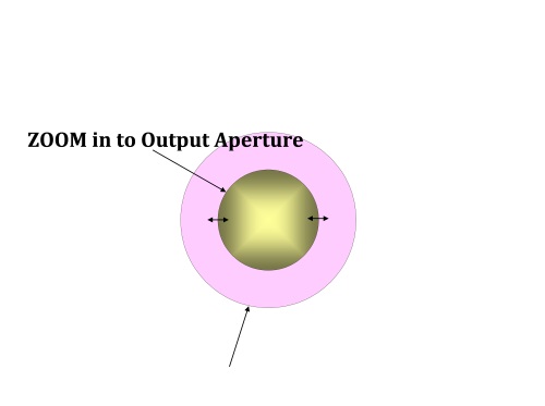
Fig. 7: Option 2b: Reduce the input cone sufficiently so that variations in tilt result in the reflected output cone remaining completely within the output aperture
For option 2b if the output aperture is already small (2c – (Combination of 2a & 2b) Reduce the input cone and enlarge the output aperture sufficiently so that variations in tilt result in the reflected output cone remaining completely within the output aperture.
The tradeoff in this solution is that the entire output lens is not used; consequently a smaller and potentially less expensive optical element cannot be employed.
Potential Barriers
High Demagnification Systems
In high demagnification systems it may not be possible to increase the size of the output aperture because the resulting F# on the demagnification side (i.e. Fig. 8 ).

Fig. 8: Example – F/28 to F/15 in 20x System Results in F/1.5 to F/0.9
Consequently one of the overfill methods (Option 1) or a decrease in the illumination cone (Option 2b) must be considered instead.
Photon Critical Systems Trade-offs
As previously mentioned, Option 1 is not desirable for systems which cannot afford to discard light. Therefore Option 2 will be the preferred solution. If the system is also a high demagnification system then the only remaining option is 2b.
Figure 9 shows the DMD output aperture diameter versus de-magnification factor. This assumes a practical limit of F/1 on the image (target) side of the lens. The red curve is the output aperture diameter. The blue curve is the allowable illumination diameter that still compensates for ±1° variation in tilt. Specifically it is the output aperture diameter less 4° (that is, the total variation of 2° times the factor of two that results from reflection). It is clear from the graph that there is practical limit when the de-magnification factor approaches 15x. If you are contemplating a system with higher levels of demagnification please contact TI regarding possible options.
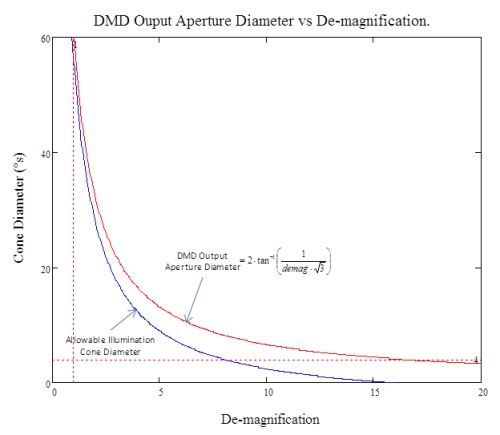
Fig. 9: DMD Output Aperture Diameter vs. De-magnification Factor
DMD production tilt variation needs to be considered when designing systems with small output apertures. Two basic methods have been discussed to help build systems that accommodate tilt variation. One method uses aperture overfill, but has the tradeoff of discarded light. The other method uses aperture underfill and may require larger optical elements, but captures most of the light.
The designer must choose the best compromise between the degree of tilt tolerance, demagnification level and cost of optical elements for their unique system.
If the system is designed with less than ±1° of tilt tolerance, mechanical adjustment for a nominal tilt range of 12° ±1° should be included in the design to tune each device.
More information
For more information, please visit www.ti.com/mems or post a question on the Texas Instruments Engineer to Engineer (E2E) community forums: TI E2E Forums.
For assistance with product and system designs, please contact a DLP Design Houses: DLP Design Houses.
Advertisement
Learn more about Texas Instruments


