Design engineers that are in the know are taking advantage of advances in magnetic component design. There have been big changes in power conversion architecture in recent years, brought on by moves to higher frequency converters with smaller proportions and the lower voltages required by today's digital systems.
Inductor and transformer companies have some new tricks up their sleeves as well. Here are two that you should be aware of.
Flat wire inductors
The “skin” effect occurs at higher frequencies, where electrons travel along the surface area of the conductor rather than through the entire cross-section, creating a higher AC impedance. Flat wire designs have approximately 60% greater surface area than their round wire equivalents, for the same cross-sectional area. Also, the fill area is increased for flat wire designs, allowing for a 95% winding factor and yielding lower resistance, and higher power capability for the same size.
One example is the Bourns SRP7030F flat wire inductor with a 7-mm square footprint and 3-mm height, and a higher inductance and higher saturation current than round wire equivalent parts. The shielded inductor series offers several alternatives for high-current, high-frequency designs up to 5 MHz and saturation currents to 60 A. The recently released SRP4020 inductor measures 4 mm square by 2 mm tall and provides 0.22−2.2-μH inductance at up to 10 A.
Würth Electronics's magnetically shielded high-current flat wire inductor WE-HCB series comes in an 18 x 18 x 9-mm package. This series offers saturation current ratings up to 65 A and low core losses with inductance values from 0.82 to 47 µH.
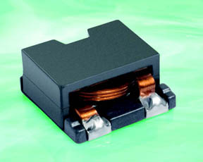
Fig. 1: Coilcraft's ST598PTA flat wire inductor.
Coilcraft has the ST598PTA series of inductors with current handling capability up to 43 A and flat wire winding that keeps the overall height to just 6 mm. The 0.5 x 0.5-mm devices weigh just 2.6 to 2.8 g and operate from –55° to 85°C with Irms (20°C rise) currents of up to 13 A. Typical SRF is from 200 to 24 MHz, with inductance from 0.33 to 10 µH.
3-D inductor integration
Inductor design is a critical piece of the modern power system design — if not the critical piece. Inductors must be designed sufficiently large enough to achieve low DCR, low copper loss, and low core loss, while maintaining a reasonable operating temperature. Many applications have limited space on the circuit board and an undersized inductor is sometimes used. As a result, the designer either has to use a bulky heat sink or live with hot spots, poor reliability, and poor efficiency.
A 3-D stackable inductor structure addresses both the space and efficiency constraints. In this structure, the inductor can be designed almost as large as the entire power module footprint and installed over the other components. Fig. 2 shows the cross-sectional view of two types of power module structures.
The standard inductor structure also prevents efficient top and bottom side cooling. The advantageous HDA power module structure with 3-D inductor integration single-layer copper lead-frame offers similar routing capabilities to a dual-layer PCB, but with a much higher thermal conductivity. By installing the inductor on top of other components, the space along the Z-axis is efficiently utilized. The module footprint area is reduced, while minimizing the inductor DCR and core loss. Furthermore, heat concentration at the inductor is easily avoided due to the reduced inductor loss and effective large heat dissipation area.
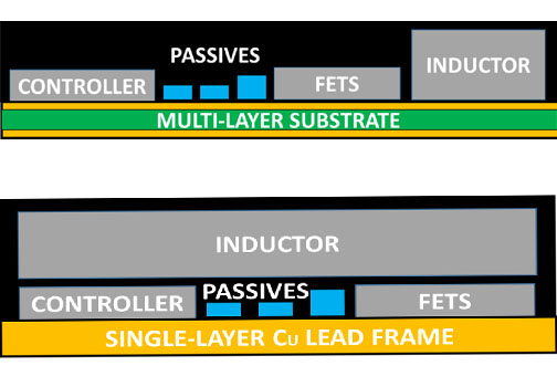
Fig. 2: A power module cross-sectional view with multi-layer substrate compared to a single-layer substrate and 3-D inductor integration.
As an example, Intersil’s ISL8272M is a 50-A step-down PMBus-compliant power module, which offers very high current capacity from a 18 x 23 x 7.5-mm HDA package.
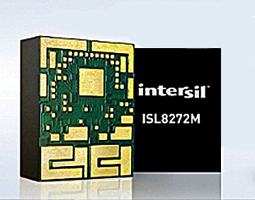
Fig. 3: A 50-A step-down PMBus-compliant power module.
The module's full load efficiency reaches 88.3% and Vin is 4.5 to 14 V. Two windings are built on a single core such that the magnetic fluxes are partially cancelled, reducing both the inductor size and core loss. Phase-interleaving allows further reduction of input capacitor size and output voltage ripple. The module PWM loop controls are implemented digitally using fast A/D converters, and complex control loops can be implemented.
Advertisement
Learn more about BournsCoilcraftIntersilWurth Electronics Midcom


