Previously, I posted part 1 and 2 of a 3 part series on how to test your power supply design: measuring efficiency (part 1) and measuring noise (part 2). I covered various noise sources and how to properly measure them with an oscilloscope. I also discussed output errors created by line and load transients
Today, I'll touch on the third and final metric when testing power supply: measuring stability.
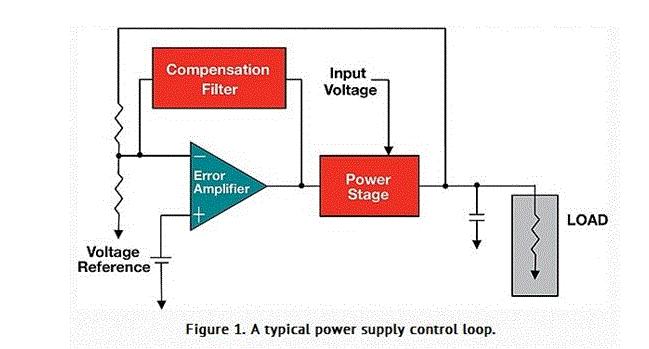
A power supply is a closed loop amplifier; it takes in electrical energy and converts it to electrical energy in another form, at a specific regulated voltage and/or current. Power supplies regulate by sensing the output and comparing a portion of it to a reference voltage. The difference between the sense signal and the reference is amplified and then used to control the power stage of the regulator to keep the voltage (or current) constant (Figure 1).

Power supplies employ negative feedback from the output back to an error amplifier to ensure proper regulation over various operating conditions (load changes, temp changes, input voltage changes, etc.). As with any stable closed-loop system, one must ensure the closed-loop gain is less than one at frequencies of operation or risk oscillation and/or other non-desirable characteristics. The negative feedback term of a power supply must be sufficiently out of phase with the input or establish a gain of less than one to ensure proper operation.
A typical regulator IC provides the necessary phase margin within the device to ensure stable operation. Like any engineer, an IC designer works with operating limit assumptions and often provides control mechanisms to adjust the internal phase delay to accommodate for various load extremes. A regulator might be designed to provide 90 degrees of phase margin with a nominal output impedance yet if the impedance is more capacitive than anticipated the phase delay might grow to a point to where the phase being fed back from the power supply output is in phase with the internal feedback point. The reversal in phase creates positive feedback with a gain of more than one, the formula for an oscillator. We all know that this is not desirable within a voltage regulator circuit.
Many regulators provide a mechanism to adjust the internal phase delay, usually accomplished with an external compensation network employing a few passive components. In some cases the regulator does not provide such hooks and must be employed within defined operating extremes (min/max output impedance over load extremes). In any case one must be able to properly analyze a circuit to determine if design adjustments are necessary. While loop characteristics can be simulated, real world system level characteristics such as PCB and connector impedances are difficult to accurately model, especially with lower cost simulation tools. So an actual stability measurement is necessary to understand actual loop stability.
Yes, I have seen many situations where a system was released to production and later in production became unstable based on environmental changes and/or operating extremes. In these situations the prototype likely worked fine yet phase and gain margins within the power supply where were not testing during prototype test. If stability of a power supply is tested a designer identifies the problem and corrects the issue before it causes more costly production issues.

Learn more about TI Power Management Solutions
Learn how tiny analog front ends shrink test and measurement systems
Advertisement
Learn more about Texas Instruments


