An overview of industrial motors and control approaches
BY SOHAIL MIRZA
Manager, Applications
Maxim Integrated Products
www.maxim-ic.com
[Editor’s Note: This is part 1 of a two-part series. For part 2. go to http://bit.ly/ic5dUy]
Electric motors are said to consume nearly 50% of the world's electricity. Industry is focused on replacing inefficient constant-speed drives and motors with microprocessor-driven variable-speed units. New motor-control technology could reduce energy consumption by 30%.
While variable-speed controllers and motors cost a bit more, the forecasted energy savings and increased motor functionality should offset those initial expenses within a few years. The dc, brushless dc, and ac induction motors are the popular types today, each with their own unique characteristics, but they all operate on the same basic electromagnetic principles.
DC motors: low cost and accurate
A dc motor was among the first motor types put to practical use, and it is still popular where low initial cost and good performance are required. In its simplest form, the stator is a permanent magnet and the rotor carries an armature winding connected to a mechanical commutator.
The magnet establishes the field flux, which interacts with the armature current to produce torque. The motor's speed is controlled by adjusting the dc voltage applied to the armature/commutator.
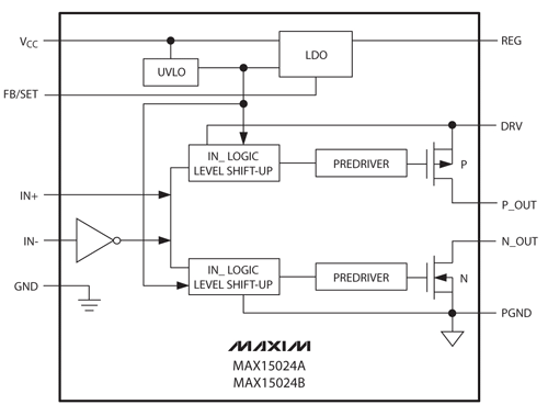
Depending on the application, a full-bridge, half-bridge, or just a step-down power converter is used for the supply to drive the armature. A number of companies now make gate driver ICs like the MAX15024/MAX15025 that ease converter design problems. The MAX15024’s source-and-sink output transistors have independent outputs allowing control of the external MOSFET’s rise and fall time. An integrated adjustable LDO voltage regulator provides gate-drive amplitude control and optimization and the chip can sink an 8-A peak current and source a 4-A peak current (see Fig. 1 ).

Fig. 1: A single-channel gate driver for high-current power conversion FETs.
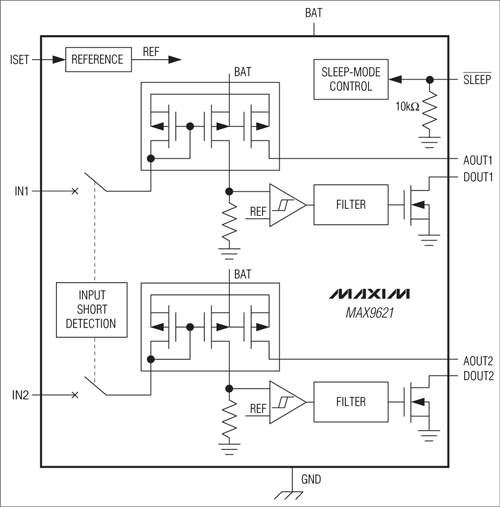
To meet speed and accuracy requirements for dc motors, a microprocessor-based closed-loop control system and information about rotor position are essential. A Hall-effect sensor with an interface like the MAX9621 dual-channel device can deliver accurate rotor position (see Fig. 2 ). The IC provides supply current and ESD/overvoltage protection for the Hall circuit.

Fig. 2: The MAX9621 connects the Hall-Effect sensors to low-voltage MCUs and protects the sensors from supply voltage transients.
AC induction motors: simplicity and ruggedness
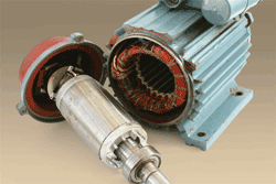
In an ac induction motor, the stator carries a three-phase winding and the rotor is a simple “squirrel cage” design with copper or aluminum bars that are short-circuited at both the ends by cast-aluminum end rings (see Fig. 3 ). The absence of rotor windings and brushes makes this motor especially reliable.

Fig. 3: Rotor and stator of an induction motor.
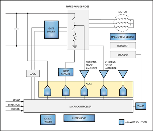
When operated from 60 Hz, the induction motor operates at a constant speed, but with power electronics and a microprocessor-based controller the motor's speed can be varied (see Fig. 4 ). The variable-speed drive consists of an inverter, signal conditioner, and MCU-based control. Many companies make half-bridge drivers like the MAX15024/MAX15025 that can control the inverter power FETs independently.

Fig. 4: A typical industrial motor control system for an induction motor has an MCU, multiple A/Ds and current sense amplifiers.
Precise measurement of rotor current, rotor position, and rotor speed are necessary for efficient closed-loop control of an induction motor. Maxim and other vendors offer many high-side and low-side current amplifiers, Hall-effect sensors, and simultaneous-sampling A/D converters to accurately measure these parameters in the harshest environments.
A popular closed-loop control technique called vector control de-couples the vectors of field current from the stator flux so that the currents can be independently controlled to provide a fast transient response.
BLDC yield high reliability and high output power
A brushless dc (BLDC) motor offers more output power per frame size, compared to induction and dc motors. The stator of the BLDC motor is quite similar to that of the induction motor. The BLDC motor's rotor, however, can take different forms but it is always built from permanent magnets.
Air-gap flux is fixed by the magnet and is unaffected by the stator current. Once again, the BLDC motor needs some form of rotor position sensing. A Hall-effect device embedded in the stator is commonly used. And again, the MAX9621 Hall interface chip keeps designs simple and incorporates the logic required to provide both positional and directional outputs. ■
We continue this article at http://bit.ly/ic5dUy
Advertisement
Learn more about Maxim Integrated


