The benefits of direct-conversion receiver designs
The performance and merits of a direct-conversion receiver signal chain in the context of 3G and 4G wireless cellular apps
BY RAKESH SONI and ERIC NEWMAN
Analog Devices, Norwood, MA
http://www.analog.com
Cellular operators have longed for the ability to deploy versatile wireless infrastructure that can be field programmed to serve a range of cellular services. Ultimately the wireless infrastructure deployed in areas of heavy cellular traffic needs to offer dynamic flexibility to allow the radio hardware to adapt to changing signal conditions.
Multistandard/multiband radio designs help to resolve the dilemma by providing equipment provisioning that can be tailored to fit the needs of the deployment. Modern direct conversion provides a compelling solution for field-programmable radio designs and offers a cost benefit and potential performance advantage over traditional receiver solutions.
In addition, direct-conversion architectures offer more freedom in addressing multiple bands of operation using a single hardware solution. This promises to be a more cost effective solution and is now enabling high-performance multistandard/multiband radio designs. This article will discuss the performance and merits of a direct-conversion receiver signal chain in the context of 3G and 4G wireless cellular applications.
A high-performance direct-conversion signal-chain lineup
A direct-conversion receiver directly demodulates an RF modulated carrier to baseband frequencies, where the signal can be directly detected and the conveyed information recovered. The direct-conversion architecture was originally developed in 1932 as a replacement to superheterodyne receivers.
The reduced component count that resulted by eliminating intermediate frequency (IF) stages provided an attractive solution. By eliminating any intermediate frequency stages and directly converting the signal to effectively a zero-IF frequency, the image problems associated with superheterodyne architectures could be ignored.
However, other challenges associated with direct conversion, including LO leakage, dc offsets, and distortion performance, have made practical implementations difficult. Recent advances in integrated RF circuit technology now allow the traditional direct-conversion (homodyne) architecture to be applied for broadband high-performance receiver implementations.
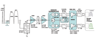
Fig. 1. Recent advances in integrated RF circuit technology now allow the traditional direct-conversion (homodyne) architecture to be applied for broadband high-performance receiver implementations, as shown above.
A wideband direct-conversion receiver is presented in Fig. 1 . Some of the more critical component specifications are highlighted within the signal chain. The receiver signal path begins at the antenna port connection into a duplexer.
Duplexers are often used in frequency-domain duplex (FDD) systems such as W-CDMA and some versions of WiMax. The duplex filter network ensures that the transmitter does not generate too much unwanted energy outside of the licensed frequency band, while helping to reject any unwanted out-of-band signals from overdriving the input of the receiver.
Typically, several low-noise amplifier stages will follow with additional band selective filtering and padding/matching networks designed to optimize performance over the frequency range of interest. The LNA stages used for demonstration purposes offer very good broadband performance and enhanced narrowband performance with the addition of external tuning networks.
In applications where the receiver needs to address a very broad range of frequency bands, it may be necessary to use a switch matrix to configure different antenna networks and LNA stages that have been optimized for specific frequency bands. After the low noise front-end, the desired carrier frequency is down-converted to baseband using an IQ demodulator.
A local oscillator (LO) is applied to the I and Q mixers at the same carrier frequency as the wanted signal. This generates sum and difference frequencies at the baseband I/Q output ports, where low pass filters heavily reject the summation frequency and allow only the difference frequency to pass.
For a zero-IF scenario, the difference frequency reveals the baseband envelope of the wanted signal. It is often advantageous to scale the magnitude of the filtered baseband I/Q signal with variable-gain amplification.
The VGA allows the I/Q signal levels to be adjusted to an optimum level for analog-to-digital conversion. In general, additional filtering may be applied before the analog-to-digital converters (ADCs) to ensure that high-frequency noise and potential leakage or interfering tones do not alias back into the desired signal analysis bandwidth.
Receiver dynamic range
The receiver uses high-performance RF integrated circuits, which offer broad frequency coverage and high instantaneous dynamic range. Instantaneous dynamic range is a critical specification for any receiver that needs to operate in a multicarrier environment where wanted signals may have neighboring interfering signals of significantly greater power levels.
Two-tone SFDR can provide system designers with a more accurate prediction of nonlinear behavior. It is common practice to test a receiver’s resilience under large-signal-blocking conditions using single tone and two-tone interfering signals. By studying the nonlinear behavior of the receiver under two-tone excitation, it is possible to calculate various intercept points that help to quantify and model the distortion performance and overall dynamic range capability of the receiver.
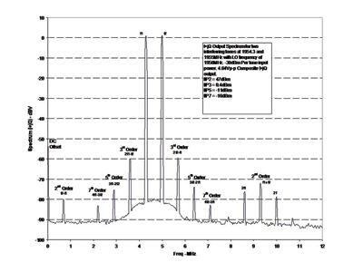
Fig. 2. Shown above is the two-tone intermodulation performance of receiver in Fig. 1.
Figure 2 depicts the I + jQ output spectrum of the receiver when presented with two large CW interfering tones that are in close proximity to the intended wanted signal frequency. Under this test case, the input signals were applied at –30-dBm input levels. This represents a pessimistic blocking scenario that is much more severe than any standard specified blocking test conditions as required in 3G and 4G cellular systems.
When sampling a signal near or at baseband frequencies, harmonic distortions from second-, third-, fourth-, and even fifth- and seventh-order nonlinearities may limit performance under large-signal input conditions. In particular, the nonlinear behavior of the I/Q demodulator needs to be sufficiently adequate to ensure that intermodulation terms generated from both the wanted and unwanted signals do not corrupt the desired signals of interest.
Rather than focusing primarily on third-order intercept point (IP3) — a common distortion metric that is a focal point in most narrowband IF sampling receiver designs—it is also important to focus on distortion terms due to even and odd-order nonlinearities. Such nonlinearities are often quantified using metrics of IP2, IP4, and IP5. In general it is important to review all spurious signals arriving within the analysis bandwidth of the receiver under worst case input conditions to ensure robust operation.
Under such severe blocking conditions, intermodulation products due to high-order nonlinearities may fall in band and desensitize the receiver. The more critical nonlinear terms are labeled in Fig. 2.
Note how odd-order terms fall close to the fundamental input tones. This helps to explain how close-in interfering signals may generate intermodulation products that fall into the band of the desired signal. The difference frequency of the interfering tones (f2 – f1 ), a result of the finite second-order nonlinearities of the receiver, may also fall within the desired signal band when using direct-conversion architectures.
As an example, ADIsimRF, a free online signal chain calculator from Analog Devices, was used to model the dynamic noise and distortion characteristics of the receiver under various test conditions. The nonlinear intercept performance was modeled and measured out to seventh-order nonlinear terms and compared against the cascaded intercepts predicted using ADIsimRF.
By reviewing the nonlinear behavior of the individual components and the overall cascaded results, the receiver lineup could be better optimized for the highest level of instantaneous dynamic range performance. Using this approach resulted in a highly sensitive receiver with
LO leakage and dc offset desensitization
Any leakage of the local oscillator emanating back toward the RF input port may reflect back into the receiver and self mix with the LO. The self-mixing results in a squaring of the LO waveform which generates a second harmonic, usually at very high frequency and heavily attenuated by baseband filtering, and a dc offset which will fall in band for a direct-conversion receiver. Note the dc term in Fig. 2.
Dc offset calibration and correction methods are often required in any baseband sampled system. A residual dc offset is equivalent to an interfering signal within the analysis bandwidth of the signal. Several techniques can be applied to mitigate the problem, including dc tracking and cancellation, ac coupling at baseband, or simply by selecting components with good dc characteristics including high even-order distortion performance.
Quadrature imperfections and image rejection
I/Q amplitude and phase mismatch can cause degraded SNR performance. In an ideal I/Q demodulator, the baseband I/Q signals share a perfect 90° phase relationship between I and Q vectors, and are said to be in perfect quadrature. Under such conditions the discrimination of symbols in digital domain can be easily determined by the instantaneous I/Q vector trajectories.
When I/Q mismatch plagues the system, the I/Q symbol vectors will suffer from amplitude and phase errors that will degrade the recovered SNR for the signals of interest. Static I/Q impairments may be corrected using digital techniques.
It is important to study the effective image rejection performance of the direct-conversion receiver versus signal level and offset from carrier frequency. An understanding of the single tone I/Q impairments of the receiver helps simplify the process of interpreting the measured performance when a modulated signal is applied.
MER performance
Modulation error ratio (MER) is a measure used to quantify the modulation accuracy of a digital radio transmitter or receiver. In a perfectly linear and noiseless system, the signal received by a receiver would have all I/Q symbol trajectories mapping to the exact ideal signal space constellation locations, but various imperfections in the implementation (such as magnitude imbalance, noise floor, and phase imbalance) cause the actual measured symbol vectors to deviate from the ideal locations. The direct-conversion receiver shows exemplary MER performance levels for various modulation schemes. Figures 3 and 4 show MER performance over input power for 10 MHz wide OFDMA, WiMAX, and WCDMA signals, respectively.
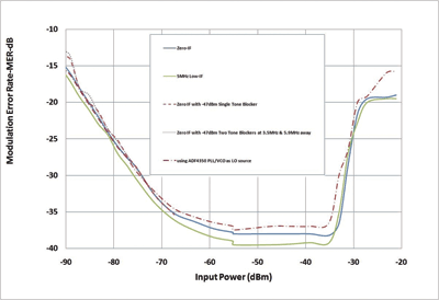
Fig. 3. MER vs. RF Input power for a 10-MHz OFDMA WiMAX signal.
In general, a receiver exhibits three distinct MER limitations versus received input signal power. At strong signal levels the distortion components falling in-band due to nonlinearities in the receiver will cause a strong degradation to MER.
At medium signal levels where the receiver is behaving in a linear manner and the signal is well above any noise contributions, the MER reaches an optimum level that is dominated by the quadrature accuracy of the demodulator, filter network and variable-gain amplifier (VGA) , and the precision of the test equipment.
As signal levels decrease such that noise is a major contribution, the MER performance versus signal level will exhibit a dB-for-dB degradation with decreasing signal level. At lower signal levels, where noise proves to be the dominant limitation, the decibel MER proves to be directly proportional to the SNR.
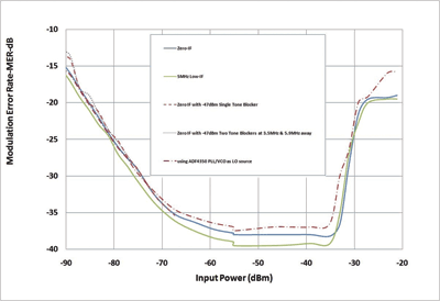
Fig. 4. MER vs. RF Input power for a WCDMA signal for zero IF, low IF, and blocker cases.
A closer look at Fig. 4 reveals the resilient performance of the receiver under various scenarios. One expects the 5-MHz low-IF case to be the most promising since it is sheltered from any dc offsets and flicker noise contributions that are associated with a zero-IF case. At lower power levels, the noise performance of the receiver is fairly constant. Even in the presence of a single tone or two tone blockers (a common test case for W-CDMA Base-Station requirements), the noise figure deviation is well within 1 dB.
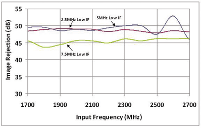
Fig. 5. Image Rejection vs. RF Frequency for various WCDMA IFs.
The image rejection ratio is the ratio of the intermediate frequency (IF) signal level produced by the desired input frequency to that produced by the image frequency. The image rejection ratio is expressed in decibels. Appropriate image rejection is critical because the image power can be much higher than that of the desired signal, thereby plaguing the down-conversion process.
Figure 5 shows the image rejection vs. multiple IF frequencies for W-CDMA. The receiver offers excellent uncalibrated image rejection performance. Through additional digital correction it is reasonable to achieve more than 75 dB of image rejection, allowing direct-conversion receivers to simultaneously capture several adjacent signals of severely different power levels (a key feature for multicarrier receiver designs). ■
Advertisement
Learn more about Analog Devices


