If you were a mountain climber using a rope to get up the sheer face of a cliff, would you rather have a nice round rope in your hands, or would you rather be hanging on to hundreds of straight filaments, each independent, and hopefully each bearing part of your weight? If you had to choose one of these designs on which to hang the survival of your communication network, which design would it be?
What is helically stranded?
Since the dawn of time, with his interest in combining filaments, strands, fibers, or other elements into thread, yarn, cords, ropes, or lines, these elements have always been twisted together. More recently, virtually all wire ropes (electrical conductors made of multiple smaller wires and electrical cables made of multiple conductors) have been twisted or “helically stranded” together. The term “helically stranded” comes from the fact that each element of such a twisted together cable forms a helix (Fig. 1). The “lay length” is the length along the cable required for one element to go all the way around a cable — from the top, around to the bottom, and back up to the top.
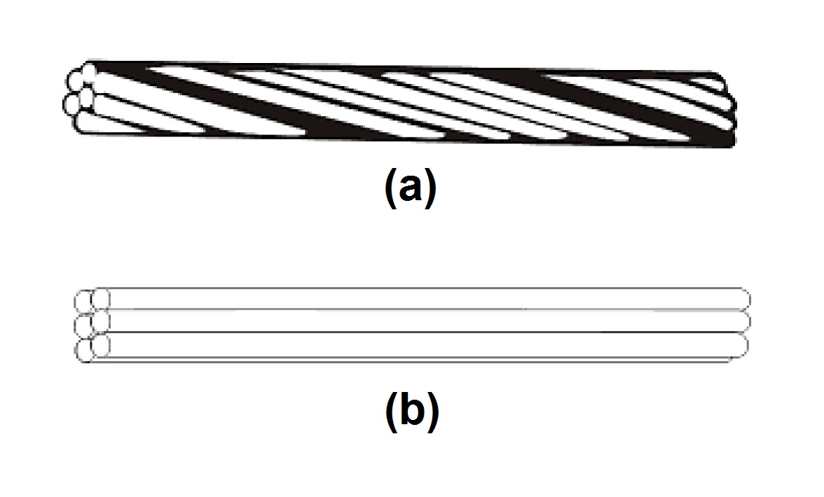
Fig. 1: Helically stranded construction creates a rounded cable (a) that is inherently stronger than one using straight lay construction (b).
Why helically stranded?
The helically stranded design is not a quirk, but a tried and time tested design and construction for cables of all kinds that has proven to offer many benefits, such as:
- All the many elements of the cable form a structure with a round cross section.
- A round cross section offers the least surface area for the enclosed volume. Therefore, when a rope slides across another object, there is less surface contact, friction, and wear for any given diameter or strength of the rope or cable.
- The cable elements are kept together despite bending and turning of the cable, because each helical element is always pulled toward the center of the cable. This helps maintain a round cross section despite radial forces (perpendicular to the length of the cable) on the cable.
- Since the helical elements are always pulled toward the center of the cable, and toward each other, there is increased friction among the elements so that load on any one element is shared with its adjacent elements, and in a short distance, among all the elements in the cable.
- Stresses on each element of the cable are averaged out and distributed among all the elements.
- As a cable is bent, each cable element rotates around the bend so that it is on the inside of the bend for a part of its length and on the outside for the next part. The tensile and compressive forces on the cable element average out within the “lay length”.
Fiber optic cables
Helical stranding is of particular importance in the construction of fiber optic cables. Typically, fiber optic cables contain multiple optical fibers and a number of aramid yarns serving as strength members, all surrounded by a plastic jacket. All the mechanical factors relevant to the physical characteristics and
performance of any cable apply. In addition, the glass fibers are sensitive to bending in two ways not found in elements of other cables.
- Excessive fiber bends or numerous “microbends” may cause significant signal loss that can degrade or prohibit system performance.
- Bends place the outer surface of the glass fibers under stress leading to the growth of any surface imperfections or microcracks. This growth of microflaws is known as “fatigue” and leads to “fatigue failure” which is fiber breakage.
In a fiber optic cable, helical stranding reduces the stresses that the fibers may be subject to during installation or in the installed condition.
Helically stranded cable tends to stay round even when pulled around a bend or tight corner. This tends to limit the cable bending and associated stress on the fiber. In the case of a non-stranded or “straight lay” cable, each cable element essentially stands alone, and is unable to offer any resistance to bending. When a straight lay cable is pulled across a tight corner, it flattens its outer jacket against the fibers, which are then subjected to a great deal of stress and are highly likely to break. Even in a moderate bend in a large smooth duct, the cable flattens increasing surface area in contact with the duct, increasing friction and pulling force required during installation. A cable in this condition essentially has its fibers separate from whatever strength elements there may be, and is subject to both permanent stress from the installed condition and future stress from crush forces from additional cables being pulled in the duct.
In a helically stranded cable, the cable elements are positioned in the cable cross sectional area during stranding. The elements always pull toward the center of the cable, and their relative positions remain predictable and unchanged over the life of the cable. Generally, the optical fibers of such a cable are placed near the center of the structure. This minimizes the stress when the cable is bent because while the outer curvature of the cable is under stress, the inner curvature is under compression, leaving the center of the cable essentially neutral. In addition, the outer elements of the cable are the aramid strength members. These outer elements provide cushioning for the fibers when the cable is subjected to crushing forces, and protection from cut through.
In a straight lay cable, the fibers tend to be bunched on one side of the other cable elements, since there are no helical stranding forces to keep them centered or to offer any predictability to the configuration of the cable core. This bunching is quite likely since the fibers are mechanically different from the aramid strength members and react to mechanical forces on the cable in a fashion distinct from the aramid yarns. In this case, if a fiber is on the inside edge of the cable core in a bend, it is subject to compression that can cause macro or microbending and optical loss associated with the bending, and ultimately fatigue failure. If the fiber is on the outside of the cable core in a bend configuration, it is placed under elongation stress causing growth of imperfections in the glass of the fibers and could ultimately cause fiber breakage.
An interesting side effect of the bunching and uncertain location of the elements of the cable core is that it requires the outer jacket to be loosely “tube extruded”. If the jacket were tightly extruded, the hot material of the jacket could fuse into the plastic buffered material of the fibers during extrusion. This could lead to future bend losses or fiber breakage as the cable core and fibers move relative to the outer jacket. Unfortunately, this side effect aggravates the drawbacks of the straight lay design because a loose outer jacket is essentially a hollow PVC tube containing some fibers and aramid strength members. Much like a drinking straw, this tube has little resistance to collapsing when it is bent sharply or kinked, again leading to fiber stress and breakage.
When a helically stranded cable is bent, the helical path taken by each fiber insures that the stresses it is subjected to are distributed and averaged over the lay length. In half the lay length, the fiber is both at the “top” and “bottom” of its helix, or in the case of the bent cable, both on the outside and the inside of the curve. Therefore, in half the lay length, the fiber is subjected to both tension and compression, which average out, leaving the fiber in an essentially neutral condition.
Purchasing a cable
If there is a specification associated with the purchase or submitted with the offer or quotation, insist that it include a statement, “All cable elements shall be helically stranded, with a lay length not to exceed 30 times the finished cable diameter.” Note: Relatively small cable diameters up to 3/8 inch (9.5 mm) with lay lengths of greater than 8 to 10 inches offer little advantage.
Regardless of whether there is a specification, insist on your prospective vendors submitting samples for your approval. When you receive a sample, carefully slit the outer jacket longitudinally with a knife or razor blade for a length of about 24 inches to one end of the sample. Peel open the jacket at the cable end and grasp the cable core between your thumb and forefinger. Lift the cable core straight out of the slit cable jacket without twisting or untwisting it. If the cable is helically stranded, all the cable elements will show an obvious twisting (helical path) completely around the cable core, typically every 6 to 10 inches.
When cable is delivered to your order, make sure that it is indeed all helically stranded by repeating this test. On longer delivered lengths of cable, a 24 inch slit may be made in a length that is not to be installed and the cable core pulled out of the side of the cable jacket. This should clearly show a helix with cable elements spiraling all the way around the cable core.
Advertisement
Learn more about Optical Cable


