Used primarily to achieve greater reliability/determinism, real-time test plays a big role in developing many of today’s products
BY CHRIS WASHINGTON
National Instruments
Austin, TX
http://www.ni.com
Real-time test techniques, which involve the use of a real-time environment to implement a test application, are used primarily to achieve greater reliability and/or determinism in a test system. As such, they play an important role in the development of many of today’s products and systems.
Examples include durability, life-cycle, and other test systems that can operate for long durations or with extended operator absence, thus requiring the superior reliability provided by real-time execution platforms. They also include environmental test cells, dynamometers, hardware-in-the-loop (HIL) simulators, and similar test systems that use closed-loop control execution, which requires the low-jitter determinism of real-time execution platforms. By examining several real-time test (RTT) applications, we can see how they are evolving to meet the challenges faced by test engineers today.
Real-time test techniques
A common real-time testing technique is the use of closed-loop control to automatically manipulate a physical variable in the test system, such as temperature, position, torque, or acceleration.
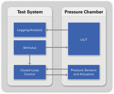
For example, when implementing an environmental test system such as a pressure chamber, the test chamber must achieve a specified state in addition to providing stimulus to the unit under test (UUT) and monitoring its response. Because the chamber pressure is affected by many variables, such as chamber leakage or varying UUT characteristics, test engineers use a closed-loop control algorithm to monitor the value of a pressure sensor and automatically adjust the compressor and relief valve command signals to follow the pressure profile specified by the test plan. To implement this automatic control, the closed-loop controller measures the state of the system and adjusts the commands applied to it at deterministic time intervals.

Fig. 1. RTT systems such as this pressure chamber use closed-loop control to automatically achieve the pressure conditions required by the test plan.
Another example is hardware-in-the-loop testing, a real-time testing application that is used to test electronic control systems more efficiently. An electronic control system consists of the electronic control unit (ECU) and the system or environment it is controlling.
When testing electronic control systems, considerations such as safety, system availability, or cost may make it impractical to perform all desired testing using the complete system. However, the closed-loop coupling between the ECU and the rest of the system makes it impossible to fully test the electronic control unit without the complete system.
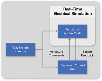
HIL simulation is a real-time testing technique that uses a software model of the rest of the system to simulate the sensor and actuator interactions between the control unit being tested and the rest of the system. This creates a virtual environment for the ECU, preserving the closed-loop coupling within the system. To accurately simulate the sensor and actuator interactions, the test system must deterministically execute model calculations at consistent, or deterministic, time intervals.

Fig. 2. Hardware-in-the-loop (HIL) testing is a real-time testing technique that uses software simulations of the missing system components to test electronic control devices.
Evolution of RTT systems
As products and systems grow in complexity, so do the testing challenges. In response to these challenges, real-time test systems are converging, producing test systems that resemble a blended set of requirements formerly found in separate real-time testing applications.
This trend can be seen in the emergence of model-based dynamometers. Typically, dynamometer test systems consist of a real-time test application using proportional-integral-derivative (PID) control algorithms to produce varying load and speed conditions for the UUT. The test system would apply static stimulus profiles to the PID controllers as well as the UUT to exercise and validate the device. An evolution from traditional dynamometers, model-based dynamometer systems use models to implement advanced control algorithms as well as generate dynamic stimulus profiles for the test system.
Engineers at Wineman Technologies (www.winemantech.com) used the National Instruments RTT platform to produce such a system in the form of a six-wheel independent chassis dynamometer. In order to adequately test their vehicle, the dynamometer needed to be able to produce test conditions that could simulate vehicle maneuvers over varying terrain.
For example, the model-based dynamometer had to be able to achieve a state in which two wheels were driving in snow, one wheel was slipping in mud, two wheels were traveling over loose gravel, and another wheel was off the ground. Furthermore, the system had to simulate the terrain transitions from wheel-to-wheel as the vehicle executed maneuvers.
To implement this test system, the engineers had to combine their experience in building both dynamometers and HIL simulators, creating a traditional dynamometer test system with additional features more commonly found in HIL test systems. Specifically, they added the ability to execute complex models deterministically to provide the dynamic stimulus generation of the six correlated speed/torque profiles and to implement the advanced control necessary to achieve such a task.
This convergence of real-time test requirements can also be seen in an application by European research organization Robotiker-Tecnalia (www.robotiker.es). During their research and development of hybrid-electric vehicle (HEV) power train systems, engineers used the NI real-time testing platform to create a specialized HIL test system.
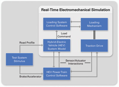
Instead of providing a completely electrical simulation of the vehicle’s sensor and actuator interactions with the ECU, they replaced the power train’s traction drive software models with the actual electromechanical components. They then connected them in-the-loop with the software models that simulated the rest of their vehicle to achieve a more accurate and flexible test system (see fig. 3 ).

Fig. 3. Mechanical components are added to an HIL simulation to provide more efficient HEV power train system development and validation.
Because a physical component had been added to the simulation, they needed to add a loading mechanism for the traction drive so that the simulation could command its loading conditions. The HIL simulator provides the simulated load values to the loading mechanism controller which applies physical load to the traction drive via mechanical coupling.
When implementing this specialized HIL test system, Tecnalia engineers had to create both an HIL simulator and a dynamometer-based loading system that worked together to provide an electromechanical simulation of the HEV power train.
Consumer expectations, regulatory bodies, and competitive pressures are pushing products to new levels of complexity at an increasing pace. As companies try to balance this explosion in complexity with shorter development cycles, greater reliability requirements, and fixed or shrinking budgets, real-time testing techniques are playing an increasingly critical role in the development process. ■
Advertisement
Learn more about National Instruments


