MARCELO SCHUPBACH,
Technical Marketing Manager,
Cree
www.cree.com
Over the past five years, the number of photovoltaic installations has increased significantly, while the cost continues to drop. However, the levelized cost of electricity for any photovoltaic installation needs to be cut in half in order to become competitive with other low cost power generation alternatives (such as coal fired power plants). Silicon carbide (SiC) power devices have demonstrated the potential to reduce the size, weight, and material costs of the inverter while increasing its efficiency, power density, and switching frequency. This, in turn, helps to significantly reduce the levelized cost of electricity for new photovoltaic installations.
SiC MOSFET gains in PV inverter
The performance, efficiency, and cost improvements realized by changing from an inverter design based on silicon (Si) IGBTs to SiC MOSFETs can be observed in virtually any string inverter topology. In Fig. 1, the simulated efficiency for high speed Si IGBTs and SiC MOSFETS is charted against switching frequency for five different 50 kW inverters using a range of two- and three-level topologies similar to Si IGBT-based string inverters that are in production today. This figure compares the following: 1) a classic two-level Si IGBT inverter topology using the latest high-speed 1200 V IGBT, 2) a three-level, neutral point clamped (NPC) Si IGBT inverter using the latest Si 650 V IGBTs, 3) a three-level, T-type Si IGBT (or MNPC) topology using both 650V and 1200V IGBTs, 4) a classic two-level SiC MOS inverter topology using a C2M 1200 V SiC MOSFET, and 5) a three-level, T-type SiC MOS topology using a C2M 1200 V SiC MOSFET. All five inverters were calculated with the semiconductor loss included, using an assumed junction temperature of Tj = 150°C, VDC bus = 800 VDC , Vout = 480 VAC rms , and fout = 60 Hz.
The most significant efficiency improvements were achieved when Si IGBTs were replaced with SiC MOSFETs in any given topology.
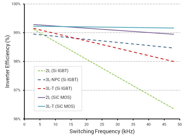
Fig. 1: Five different 50 kW inverters using high speed Si IGBT and SiC MOSFET devices with inverter efficiency measured as a function of switching frequency.
The contrast between the critical parameters of a state-of-the art, commercially available 50kW Si IGBT string PV inverter and those of a Cree-designed 50 kW SiC MOSFET string PV inverter demonstration unit (using C2M SiC MOSFETs and CPW5 Z-Rec SiC Schottky diode power modules) can be seen in Table 1. The SiC-based inverter reduces overall inverter losses by 40%, enabling a California Energy Commission (CEC) efficiency rating of 98.5%, and is approximately one-fifth the weight and volume of the Si IGBT-based inverter, as shown in Fig. 2.
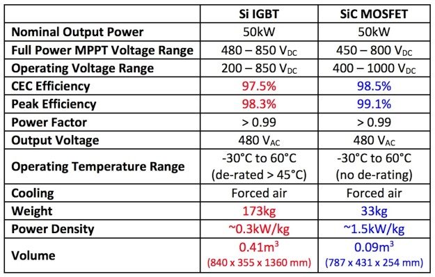
Table 1: A comparison of the key metrics for 50 kW string inverters designed using Si IGBT and SiC MOSFET technologies
The PV inverter in Fig. 2 includes a four-channel interleaved boost stage (to reduce input/output ripple current) with SiC devices operating at a switching frequency of 75 kHz. It also includes a three-phase 480 VAC inverter stage based on a three-level, T-type, mixed-voltage neutral point clamped (MNPC) topology, which is commonly employed in PV inverters of this power level. The inverter stage operates at 48 kHz, and the complete system is controlled using a TI 320F2812 DSP working at 150 MHz.
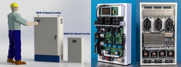
Fig. 2: (Left) Relative size comparison of a typical 50kW Si IGBT string inverter and a Cree-designed 50 kW SiC-based string inverter demonstration (pictured, front and back, on the right).
These significant performance improvements are now possible due to the inherent fundamental properties of SiC technology:
• SiC MOSFETs exhibit 6 – 10x lower switching losses than Si IGBTs, enabling them to operate at much higher switching frequencies with minimal cooling demands. [1]
• The negligible recovery charge of SiC diodes virtually eliminates diode switching losses.
• Due to higher switching frequencies, the size and weight of critical inverter components can be significantly reduced, especially for inductors and filtering capacitors [1, 2]. This reduction enables a substantial compounding effect, providing reductions in size, weight, and cost for other inverter system components, such as wiring, enclosures, and mounting hardware.
SiC MOSFET string inverter economics
By comparing the relative component costs of a 50 kW Si string inverter and a SiC-based string inverter, as shown in Fig. 3, it is clear that bill-of-materials (BOM) costs for the enclosure, inductors, and heatsinks are higher in the Si IGBT-based design. By contrast, even though the cost of SiC MOSFET devices is higher than Si IGBTs (by approximately 4x), the SiC-based inverter effectively reduces the cost of the driver components (for example, the enclosure, inductors, and heatsinks), and thus enables an overall BOM reduction of 15%.
Additionally, since less raw material is required, there is a strong correlation between power density and inverter cost, as presented in the “Technology Roadmap, Solar Photovoltaic Energy” authored by the International Energy Agency [3]. A higher power density inverter design can also have the effect of reducing manufacturing costs by enabling more automated manufacturing methods. Developing lighter, more compact inverters also significantly reduces transportation and installation costs, especially for rooftop installations, since they can be moved by hand, without requiring cranes, forklifts, or structural reinforcements to the roof. Further, compact inverter designs, by virtue of having fewer interconnections and boards, are inherently more reliable.
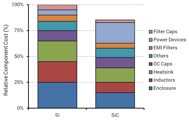
Fig. 3: Relative component costs within Si IGBT-based and SiC MOSFET-based 50 kW string inverters
Under the same input voltage condition (Vin = 500 V), efficiency plots for the commercially available Si IGBT-based 50 kW string inverter and the SiC MOSFET-based inverter demonstrate that the SiC MOSFET-based inverter delivers approximately 1% higher efficiency than the conventional Si inverter technology (Fig. 4). Although a gain of just 1% in efficiency may not seem significant, it translates into several positive economic implications for the overall system. With a 1% higher generation capability, the payback period of the PV installation is accelerated. In additional, the 1% inverter efficiency increase may be used to reduce the PV module size by 1%. Moreover, since PV modules account for almost half the total system cost, this 1% reduction in size translates into a 0.50% cost reduction for the total PV installation [3].
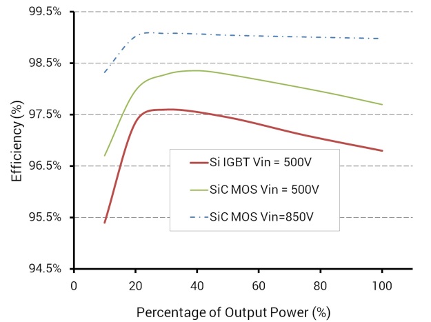
Fig. 4: Efficiency versus the percentage of output power for Si IGBT-based inverter and SiC MOSFET-based inverters .
SiC-based inverters help lower PV installation costs worldwide
As PV solar module technology has improved, the average cost for PV installations (shown in Figure 5) has fallen from approximately $4,900/kWp in 2006 to less than $1,500/kWp in 2013 [4]. Consequently, while PV solar module cost represented 70% of the overall PV system cost in 2006, it was only 50% of the overall cost in 2013. The remaining 50% of the installation cost includes both the inverter cost and balance of system (BOS) costs, such as installation, labor and materials, site preparation, transportation, and wiring.
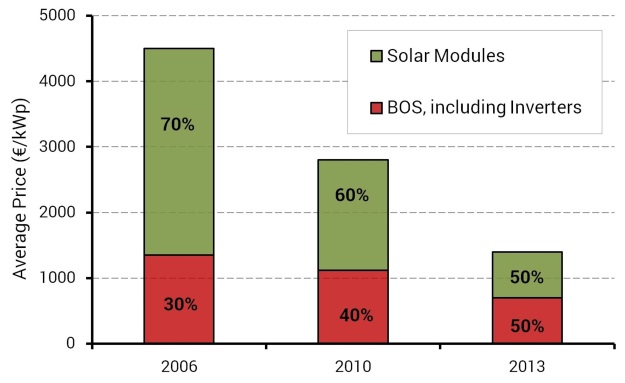
Fig. 5: Average price of 10 to 100 kWp PV rooftop systems in Germany (2006–2013).
This ongoing cost pressure has helped drive improvements in PV inverter power density from 0.08kW/kg to 0.5kW/kg, indicating a clear reduction in material usage [3]. As illustrated by the data from Europe, the actual cost of the PV inverters themselves is currently only 10 – 15% of the total cost of a typical 100kWp PV installation [4]. Thus, to achieve meaningful reductions in the overall cost for PV installations, it is going to be critical to focus on the reduction of other BOS costs (e.g., installation labor, wiring, etc.) while supporting higher levels of functionality [5].
Since SiC MOSFET-based PV inverters achieve 15% lower inverter BOM costs, there is potential to reduce total installation costs by as much as 2.3% [3]. Further, by enabling a lower overall weight and a higher power density, SiC-based inverters can reduce the typical installation costs for a PV inverter by 40%. PV inverter installation costs, along with other engineering costs, represent as much as 5% of the total PV installation expense. As such, SiC MOSFETs have the potential to deliver a 4.7% combined total reduction in the overall costs of installation, which means that a SiC-based string inverter capable of delivering this type of competitive cost savings will have a distinct advantage over traditional inverters.
In addition to improved performance and higher efficiency, SiC MOSFET-based string inverter designs have demonstrated the ability to deliver quantum improvements in power density, achieving 1.5 kW/kg and higher. These significant inverter performance improvements produce a compound effect on the overall cost of the PV installation, reducing the inverter, installation, and engineering costs, as well as the PV module count. SiC MOSFET inverter technology is poised to significantly reduce both the installation and operating costs for new PV installations, and, in turn, to drive down renewable energy costs, improving the global rate of adoption for PV energy.
References:
[1] Liu, J.; Wong, K.; “Silicon carbide (SiC) 10kW interleaved boost converter achieves 99.1% peak efficiency,” Bodo’s Power Systems, December 2012.
[2] Rice, J.; Mookken, J.; “Economics of high efficiency SiC MOSFET based 3-ph motor drive,” Power Conversion and Intelligent Motion (PCIM) Europe, 2014. Nuremberg, May 2014.
[3] Maria van der Hoeven, “Technology Roadmap, Solar Photovoltaic Energy,” International Energy Agency, https://www.iea.org/publications/freepublications/publication/TechnologyRoadmapSolarPhotovoltaicEnergy_2014edition.pdf, 2014.
[4] Prof. Joachim Luther, Solar Photovoltaic (PV) Roadmap for Singapore (A Summary), https://www.nccs.gov.sg/sites/nccs/files/Roadmap_Solar_20140729.pdf, 2014.
[5] Joyce McLaren, “Advanced Inverter Functions To Support High Levels Of Distributed Solar,” National Renewable Energy Laboratory, http://www.nrel.gov/docs/fy15osti/62612.pdf, 2014.
Advertisement
Learn more about Cree


