The longer the character count of the URL that a QR code redirects to, the more complex the code becomes. In fact, the length plus the error correction level dictates what the QR code size must be. To address this issue, it is recommended that users create a tiny URL directed to the original address, as the ideal URL should have less than 20 characters.
Generating the QR code
QR codes can be generated on several websites or tools. However, as not every tool uses the same encoding algorithm, once a QR code is generated, the creator needs to use the same source to regenerate the code moving forward to ensure the same image for all products. Though some online tools have extra options, below are the key attributes to consider during the generation.
- Error correction level: Which enables the detection of errors and reconstruction of the original, error-free data. Suggested: M, which allows 15% of codewords to be restored.
- Color: Almost all QR reader applications are programmed to read a black or dark QR code over a clear background. If the background is dark (i.e. the solder mask is red, blue, black, green, etc.), the QR code needs to be inverted before it is implemented on silkscreen. If the solder mask is white, the QR doesn't need to be inverted.
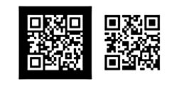
- Size: The final QR code once imported should be >0.5 in. Some image to DXF conversion tools can do a resample. If not, the correct pixel size can be chosen during generation.
- Margin around QR code: The ideal margin is 20%, though Freescale has successfully used 10% margin on QR codes.
- Encoding: Suggested UTF-8.
Convert the QR code to DXF
Once the QR code is generated (.JPG, .PNG, .TIFF, etc.), it needs to be converted to .DXF. Several tools are available on the market to manage this process.
- Before converting the image to .DXF, the code should be the correct color, based on solder mask color.
- Images can be converted into vectors or shapes, depending on the tool used.
- The image should be resized to the final imported QR code.
- The minimum suggested QR code size to be readable for a 5-Mpixel cameras is 450 mils + margin. The bigger the QR code, the more easily it is scanned.
Minimum suggested QR size is as follows:
Minimum QR Code Size = (Scanning Distance / Distance Factor) * Data Density Factor
• Distance Factor: Start with a factor of 10, then reduce it by 1 for each of the following conditions: poor lighting in the scan environment, a mid-light colored QR code being used, or the scan not being done front on.
• Data Density Factor: Count the number of columns of dots in the QR code image and then divide by 25 to normalize it back to the equivalent of a Version 2 QR code.
• Scanning Distance = 3.5 in.
• Distance Factor = 7 (poor light, printed over solder mask, sometimes with traces under)
• Density Factor = 21/25 = 0.84
Minimum Size = (3.5 in. / 7) * 0.84 = 0.42 in
Once these steps are completed, the image should be saved in the .DXF format.
Import .DXF QR to Allegro
The easiest way to import and work with a QR code is to create a Mechanical symbol.
- Open Allegro PCB editor
- Go to File > New…
- Drawing type select: Mechanical Symbol
- Drawing Name: Enter name
- Browse: Find the directory where you want to keep the symbol
- Click OK
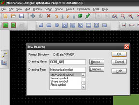
- Go to File menu > Import > DXF… > Browse and select the .DXF file.
- Set DXF units
As a tip, a large size .DXF can be used and then imported in MM (inches/25.4) to improve resolution.
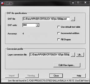
- Click on Edit/View layers
- Activate “select all” option
- Class: Select the class where imported QR should go (BOARD GEOMETRY)
- Subclass: Select SILKSCREEN_TOP
- Click “map”
- Click OK
- On the next screen, click “Import”
- If a pop-up warning window opens, close it
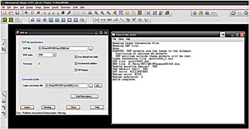
- The QR should now be imported. Measure it to make sure it meets requirements.
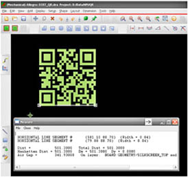
- Go to File > Save As: Select the name and directory to save it. The QR code is now a mechanical symbol and is ready to be used.
- Open your design in Allegro (.BRD)
- To import the QR, go to Place Manual found on the Advanced Settings tab and Select Library
- Return to placement list, on the drop-down menu select > Mechanical Symbols
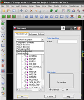
- On the Match filter enter *QR*
- Select the desired QR and place it on the board
- Once the file is placed, select it as a symbol to move it, rotate it, etc.
- Note: This activity slows down the PC, so try to leave it when the layout is about to be finished.
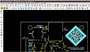
If the .DXF is a vector file, before generating gerbers select:
- Show Element > Lines
- Select one of the QR lines
- If the width is 0.00 the QR will not be correctly exported to the artwork layer so it needs to be changed to 0.01
Check the artwork layer of the gerber files to confirm that the QR was exported correctly. The board is now ready to be scanned and implemented. The same process can be used to import some images, logos, etc., to give an attractive visual to development tools.
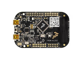
Find more information at: http://en.wikipedia.org/wiki/QR_code
Advertisement
Learn more about Freescale Semiconductor


