By Russell J. Hoppenstein, applications manager, wireless infrastructure, Texas Instruments
In the first installment of this series, “The MIMO advantage,” I covered the basics of multiple input, multiple output (MIMO). In this installment, I’ll provide the high-level calculations for implementing MIMO. The key issue is characterizing the channel. This channel characterization was not previously needed in diversity schemes, but for MIMO, it is necessary in order to fully harness the performance potential of a given system. Once you have defined the fundamental calculations, the capacity improvement of MIMO becomes apparent.
How does MIMO work?
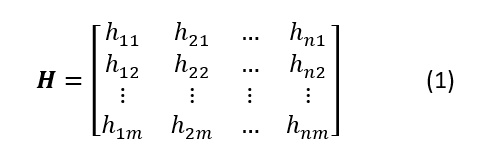
MIMO systems use multiple transmit and receive antennas. The matrix, H , encompasses all of the individual hij transfer parameters between the transmitters and receivers. Equation 1 shows theH matrix for an M transmitter by N receiver system:

Equation 2 calculates the received signal, yi , at each antenna element:

Equation 3 simplifies the expression into matrix form:

The input and output matrix size matches the number of transmit and receive antennas. The number of transmit and receive antennas may be the same, but it is not necessary. The number between the two is often not symmetric.
Equation 3 is simple. The received information, Y , is equal to the input signal, X , operated on by the channel characteristics, H , in the presence of noise and interference (n ). The goal of the system is to reconstruct the input signal given the received signal. The noise parameter is assumed to be a Gaussian zero-mean function with static variance.1
For initial simplicity, assume that the channel has a favorable signal-to-noise ratio (SNR); thus, the noise term is eliminated. Equation 4 shows the conceptually simple mathematical approach of reversing Equation 3 without noise using the inverse channel matrix:
 The original signal is recovered using the channel matrix. But how do you know the channel matrix, being that it is always changing due to physical changes in the environment? There is no way to know precisely. The system must estimate the channel characteristics. Periodically, the transmitter sends known pilot codes that the receiver uses to estimate the channel matrix, as outlined in Equation 52 :

The system knows the received signal and the predetermined pilot signal and then estimates the channel matrix. In practice, the estimation is more difficult when dealing with a non-ideal noisy channel. Pilot symbols with sufficient length are used to average out noise contribution across multiple channels.3
The information from each transmitter is received in some fashion by each of the receive antennas. Any detrimental impact — fading or interference that negatively impacts one path — likely won’t impact all paths, so there is built-in diversity or backup to recover the signal. This is not diversity in the traditional sense of just picking the best signal out of the bunch. This is actually combining the signal from each receiver to use all available power to reconstruct the signal. Nothing is wasted.
MIMO is not just immune to fading; it relies on it. How counterintuitive! Communication engineers spend their careers figuring out how to overcome the detriments of channel interference. This system needs the multipath fading to create the spatial encoding. If a MIMO system uses pure line of sight, then there is no diversity in the system. The signal processing that generates the inverted channel matrix H is close to an identity matrix, and the input signal is not very discernable. Think about solving n equations with n unknowns. That type of problem is solvable; however, if each equation is exactly the same, finding the independent variables is impossible. Multipath fading provides variations in the signal to make the equations solvable and, in turn, make the input signal reproducible.
Capacity improvement
Shannon’s limit (Equation 6) dictates the ideal capacity of a system within a given bandwidth constraint and channel noise condition:

The capacity equation derives from the mutual information between input channel (x ) and output channel (y ) across the input distribution according to Equation 73 :

In the MIMO case, the mutual information is between the input signal X and the output variable Y over all of the statistical distributions that satisfy the power constraint of a passive system such that the sum of the individual powers does not exceed the total power transmitted.4 The noise contribution is assumed to be a Gaussian zero-mean distribution and is independent of the input signal.
Equation 8 shows the simplified capacity equation. For those who crave complicated matrix algebra on random processes, see References 4 and 5.

The matrix I is the identity matrix. The variable H is the channel matrix. The parameter HH is the Hermitian transform of the H matrix defined by the transposed complex conjugate. The Pt /σn 2 term represents the SNR.
As the antenna count increases, the capacity equation simplifies to Equation 9, an approximated expression relative to the traditional single-channel case5,6 :

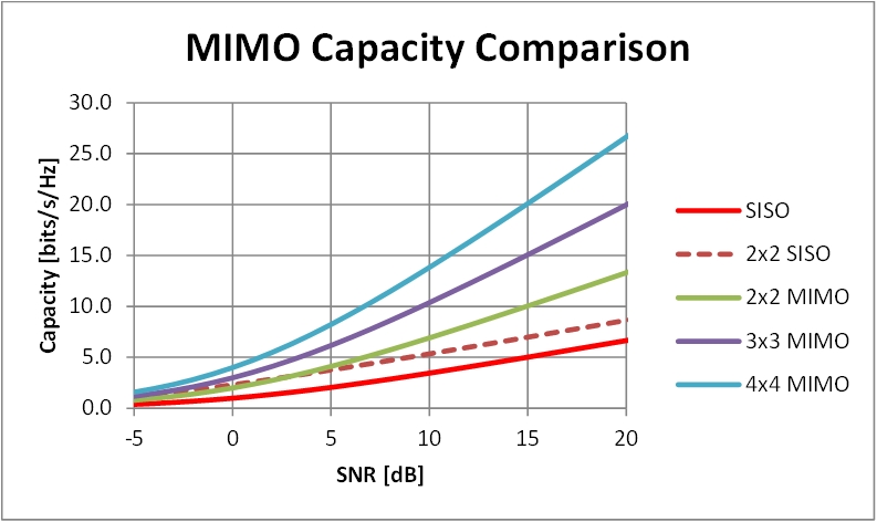
Equation 9 shows that, ideally, the MIMO capacity is a linear improvement of the single transceiver case. Fig. 1 shows the response of a single-input, single-output (SISO) system compared to a 2 × 2, 3 × 3 and 4 × 4 MIMO system across SNR performance. At higher SNR levels, the MIMO system offers significantly greater capacity benefits.

Fig. 1: MIMO capacity compared to SISO
MIMO is better than just a transmit-and-receive diversity scheme. Compare the 2 × 2 diversity scheme to a 2 × 2 MIMO system. A 2 × 2 transmit-and-receive diversity scheme provides 4× the signal power (2× from the transmitter and 2× from the receiver), which is equivalent to a 6-dB SNR improvement. At poor SNR values, the increased signal yields value, but at about 2-dB SNR, the MIMO case exceeds and outpaces the diversity scheme.
Conclusion
The MIMO system thrives in a fading, multipath environment, taking advantage of the environmental coding imprinted on the information as it propagates through the channel. The system increases capacity compared to traditional single-link and diversity-link systems. Additionally, capacity scales with the number of antenna elements. It is an expandable system ultimately limited by signal processing power and the cost/space limitations of multiple transceivers and antennas. The next installment of this series explores multi-user and massive MIMO systems.
Watch for “The MIMO advantage, Part 3: advanced MIMO applications” in the upcoming weeks.
References
1 Matthias Stege, Peter Zillmann and Gerhard Fettweis, “MIMO Channel Estimation with Dimension Reduction,” 5th International Symposium on Wireless Personal Multimedia Communications (October 2002).
2 Dominik Seethaler (January 11, 2006), “Capacity Analysis of MIMO Systems.” Retrieved from: https://www.semanticscholar.org/paper/Capacity-Analysis-of-MIMO-Systems-Seethaler/6df346f07d960a62fde885b81727130aff6297c7.
3 Jaimal Soni (August 2013), “Capacity Characterization of a MIMO-OFDM Wireless Channel with BLAST Implementation.” Retrieved from: https://uwspace.uwaterloo.ca/handle/10012/5426.
4 Bengt Holter (November 15, 2002), “Capacity of multiple-input multiple-output (MIMO) systems in wireless communications.” Retrieved from: https://www.ceid.upatras.gr/webpages/faculty/alexiou/ahts/other_pdf/6_mimo.pdf.
5 Arif Khan and Rein Vesilo (2014), “A Tutorial on SISO and MIMO Channel Capacities.” Retrieved from: https://pdfs.semanticscholar.org/9606/2e1f897c5b75dd94375a9440d4c3702410d3.pdf.
6 E. Ghayoula, A. Bouallegue, R. Ghayoula and J-Y.Chouinard, “Capacity and Performance of MIMO Systems for Wireless Communications,” Journal of Engineering Science and Technology Review 7(3) (August 1, 2014), pp. 108–111.
Related articles
Advertisement
Learn more about Electronic Products MagazineTexas Instruments


