Switches expand into bridging, and Gen 2 offers simplification opportunities
BY STEVE MOORE
PLX Technology
Sunnyvale, CA
http://www.plxtech.com
As the I/O interconnect world has transitioned from PCI to PCI Express (PCIe), bridge ICs have filled a critical role: to allow designers to continue to use existing PCI and PCI-X endpoints in PCIe-based systems. Once the majority of these endpoints go PCIe-native, as expected, the interconnect role once largely held by bridges will shift to switches, though bridges will continue to enable legacy PCI designs in the PCIe world.
Adding another dimension to this shift, designs are now migrating to PCIe Gen 2, and its 5 GT/s performance, for next-generation interconnect. And, further complicating matters, some companies have decided to call their PCIe switches “bridges.”
The outlook for the PCIe-to-PCI bridge function
The conventional PCI bus delivered a low-cost, robust and well understood interconnect standard. For most applications, the transition to PCIe from PCI has brought the benefits of cost and power reductions, smaller form factor due to lowered pin count, and increased performance.
As a result, system boards and chipsets now have several PCIe slots but limited PCI connectivity. PCIe-to-PCI bridges enable the creation of additional PCI or PCI-X slots on system boards and riser cards. This is done using the commonly available “forward mode” bridge configuration. Some bridges are also available with a “reverse mode” configuration option, which allows the creation of PCIe slots from existing PCI slots; useful for updating legacy motherboards.

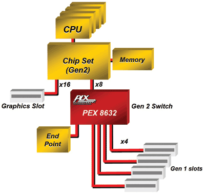
Fig. 1. A Gen 2 switch acts like a “bridge” from Gen 1 I/Os to a Gen 2 root complex.
From Gen 1 to Gen 2
PCIe Gen 2 offers twice the maximum throughput with the same number of lanes and there is now a need for something to bridge between the two standards. Here, the switch can act as bridge, as shown in Fig. 1 . It shows a Gen 2-enabled server chipset with two PCIe ports on the root complex, one of which (the x8 port) is connected to a Gen 2 switch.
This 32-lane switch is configured with six ports – one upstream x8 Gen 2 port and five downstream ports. The downstream are all x4 Gen 1 ports. The switch, therefore, acts like a “bridge” from Gen 1 I/Os to a Gen 2 root complex.
A similar system can do the opposite type of bridging, from Gen 2 I/Os to a Gen 1 root complex. Since the upstream port of the switch is only running in Gen 1 mode, twice as many lanes are needed to maintain the same bandwidth into the root complex. On the other hand, since the downstream ports are running in Gen 2 mode, only two lanes per slot are required for the same I/O bandwidth as seen in Fig. 1, which uses x4 Gen 1 ports.
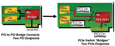
PCI-to-PCI bridges are often used to create or add PCI slots, allowing for fan-out from a host to multiple endpoints. The maximum throughput of the 32-bit 33-MHz bus on the left-hand side card in Fig. 2 is a mere 125 Mbytes/s; whereas the x16 Gen 2 slot on the right-hand side has 8 Gbytes/s available.

Fig. 2. A PCIe switch can replace a bridge for increased fanout.
Graphics adapters are advancing to offer more and more performance for ever-increasingly complex images for games and video. One way designers are doing this is by deploying multiple GPUs on a single card. This is another example of the fanout usage model except the downstream ports connected to the GPUs are x16 for maximum bandwidth. It’s worth noting in this example that in the literature for these dual-GPU cards the fan-out switch is often referred to as a “bridge,” feeding some confusion in the I/O world.
In other applications, such as Fiber Channel host bus adapters (HBAs), the full bandwidth of a x16 Gen 2 link is not required (yet). However, the use of Gen 2 links allows a lower lane count for the given bandwidth, reduces the pin count and the board’s space, simplifies layout thus reducing cost, and allows for a smaller form factor.
PCIe switches appear as bridges to the OS
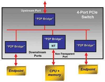
When a PCIe switch is used for fan-out below the root complex in a system, each of the switch’s ports will appear to the OS as a bridge header, as shown in Fig. 3 . This is a reflection of PCIe’s capability to maintain software backward compatibility with PCI, so migrating from PCI to PCIe does now require new drivers, unless the functionality is enhanced along with the change of interface.

Fig. 3. A PCIe switch forms a bridge hierarchy.
The topology in Fig. 3 can be looked at in two contexts. In a legacy PCI system, a system fans out through a host bridge to three bridges downstream. This allows several I/O devices to aggregate onto the system host bus. If domain isolation is required, a nontransparent (NT) PCI-to-PCI bridge is deployed.
Where the standard PCI-to-PCI bridges allow the host to look through and see the endpoints behind them, the NT bridge just looks like an endpoint to the host, and prevents the host from enumerating devices behind the NT bridge. The NT bridge allows windows to be opened through which data may be exchanged, while isolating the processor behind it and its memory space.
Transparent bridges allow systems to electrically isolate separate buses. They use a Type 1 header in their configuration status register (CSR) to indicate the existence of additional devices downstream.
NT bridges, on the other hand, maintain both electrical and logical isolation of processor domains. NT bridges forward transactions from one side of the bridge to the other, using address translation; they use a Type 0 header in the CSR to terminate discovery by the host.
Nontransparent bridging with a switch?
In a PCIe system, the host bridge is replaced by the upstream port of a four-port fan-out switch, and the downstream ports all appear to the host OS as PCI-to-PCI bridges. Many of today’s PCIe switches allow one port to be configured as an NT “bridge,” as shown in Fig. 4. The operation is the same as with an NT bridge, only now the function is performed as a configuration option for one port of the switch.

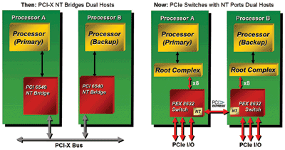
Fig. 4. A PCIe failover system can exploit a non-transparent configuration.
Another application where the switches have replaced traditional bridges is in dual-host failover systems. As shown in Fig. 4, two CPUs are deployed in each system. One is configured as the primary host and the other is there in case the primary host fails. NT bridging is used to provide domain isolation between the primary- and the backup-host CPUs.
Applications that use NT bridging include add-in cards with embedded CPUs, such as network security processors, RAID controllers and line cards, in addition to dual-host failover systems.
Switches go beyond bridging
Besides replacing a bridge, the latest Gen 2 switches have deployed several new features that enhance system performance and simplify design/debug. They include such features as read pacing and dual cast, both of which enhance throughput and reduce traffic congestion in ways not possible using bridges. Additionally, system debug features, such as packet generators, SerDes eye measurements, and performance monitoring, are being deployed in the Gen 2 switches, making it possible to optimize performance issues without external instrumentation. ■
For more on PCI Express, visit http://www2.electronicproducts.com/DigitalICs.aspx
Advertisement
Learn more about PLX Technology


