Thermal energy harvesting for distributed sensors
Thermoelectric power generation enables wireless power solutions
BY DAVE KOESTER
Vice President of Engineering
Nextreme Thermal Solutions
www.nextreme.com
The past decade has seen significant advances in distributed sensors and sensor networks. With these advances has come an increased interest in energy harvesting to provide a continuous power source that will replace or augment existing power storage systems. Energy harvesting is the process whereby a portion of energy is removed, captured, and stored from an existing source of unused but available energy. Thermoelectric power generators (TEGs) convert waste heat from thermal sources into usable electricity, thus eliminating the need to use traditional wired power sources or replaceable batteries.
System components
A thermoelectric energy harvesting system consists of two major components in addition to a heat source (Fig. 1 ), namely the thermal circuit and the electrical circuit. Thermoelectric energy conversion requires special attention to both circuits to provide optimal performance. Put another way, it is often necessary to design and build the system for a known set of conditions to provide the most efficient energy conversion.
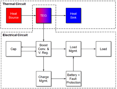
Fig. 1: Schematic of TE energy harvesting system showing breakout of thermal and electrical circuits.
Heat sources
Heat sources can take on many different forms, including hot surfaces such as pipes, furnaces, HVAC systems, engine blocks, exhaust gases, direct sunlight, and even the human body. Sources often vary considerably over time, and this must be taken into account in the design of the energy harvester.
Figure 2 shows the governing equations for thermoelectric power generation and the equivalent circuit for a thermoelectric generator (TEG). For a given temperature differential ΔT across the TEG, the device produces an open-circuit voltage Voc in series with its internal resistance Rinternal. The maximum output power produced by the TEG, when applied to a matched electrical load is also shown in Fig. 2. The output power and I-V characteristics of a TEG are shown graphically in Figure 2.
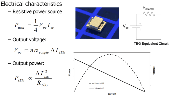
Fig. 2: Governing equations for thermoelectric power generation.
It should be noted that the maximum output power is proportional to the square of the temperature differential ΔT and inversely proportional to internal resistance Rinternal of the thermoelectric.
Heat sinks
To enable the constant flow of heat required to sustain a temperature differential ∆T, a heat sink or exchanger is required. A large percentage of thermoelectric energy harvesting applications relies on air cooling and therefore employs conventional heat sinks. In addition, these sinks are typically the lowest-cost solution and easiest to implement.
Figure 3 shows two major factors that affect the performance of heat sinks. The first of these factors is the airflow. The goal of any heat sink is to provide the lowest possible thermal resistance, thereby enabling heat flow in the system. The thermal resistance of a heat sink is very sensitive to airflow and behaves very nonlinearly, particularly at low airflow. At low airflow, the thermal resistance is very high. When airflow is essentially zero, the condition is referred to as natural convection. When the ultimate operating conditions of a thermal energy harvesting system are unknown, the worst-case scenario must be assumed, in this case, natural convection.
If airflow is known, the heat sink should be designed to operate below the knee in that curve to provide optimal performance. The other major factor to consider is the size of the heat sink. Heat sink size, like airflow, has a very nonlinear relation to thermal resistance of the heat sink. Again, it is desirable to operate just to the right of the knee in that curve to provide adequate heat sinking for the application without making the sink too large and experiencing diminishing returns on the heat sink size.
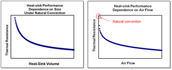
Fig. 3: Major factors that affect the performance of heat sinks.
Other aspects of heat sink design are important. For example, the fin type and spacing directly affect how well the heat sink works in natural convection versus forced airflow. Orientation of the heat sink relative to gravity is also important when operating in natural convection mode. In natural convection, the fins should either be pointing up or sideways. Fins pointing downward under natural convection substantially reduce the performance of the heat sink.
Electrical system
The electrical system, as shown in Fig. 1, includes the TEG, the voltage regulator, charge management circuitry, energy storage, and power (load) management circuitry.
Voltage regulation
Most electronic sensors require more than 1 V to operate and many require more than 3 V. Since the voltage output of a TEG is proportional to the temperature differential ∆T across the TEG, large values of ΔT are desired for most applications. In many applications, the ∆T available is fairly small meaning that the output voltage of the device may not exceed the minimum requirement. Variation in the temperature of the heat source can also lead to unstable voltage output. To address these issues, it is necessary to boost (and regulate) the voltage to the minimum, usable, constant value.
The energy harvester shown in Fig. 4 employs voltage regulation and the associated output current as a function of heat source temperature.
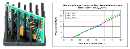
Fig. 4: An example of an energy harvesting system.
The harvester has a built-in power management system that up converts the voltage from the thermoelectric to a constant 3.3-, 4.1-, or 5.0-V output. The system is small, roughly on the order of 2 in.3 and is ideal for wireless sensors and other low-power applications.
Charge management and energy storage
There are two basic approaches to storing energy in an energy harvesting unit. These are either electrochemical cells (batteries) or capacitors. Batteries are capable of high energy storage densities compared to capacitors, and they also exhibit less leakage current than capacitors. Conversely, capacitors, and especially the super caps, have very high power densities compared to batteries, meaning they can provide high bursts of current for short periods of time. In cases where high energy storage is required but short bursts of energy is also needed, a capacitor can be placed in parallel with the cell.
Power/load management
The load management circuit is used to automatically switch the load between the regulated voltage supplied by the thermoelectric generator and the battery depending on the thermal conditions and status of the regulator output (i.e., thermoelectric generator) and discharge level of the battery. Often battery protection circuits are also incorporated to ensure that the battery is not overcharged or over-discharged.
Thermal energy harvesting systems require specific and careful optimization at both the thermal and electrical circuit levels. In particular, the thermoelectric device must be sized appropriately for the available heat and electrical load.
Optimizing the thermal circuit for the given boundary conditions is critical. The heat sink plays a dominant role in the thermal circuit, and proper design should be considered carefully. In most cases, voltage regulation is necessary as heat sources vary in both temperature and available heat over time meaning a stable voltage directly from the TEG is not possible. Onboard energy storage is an important consideration and can provide accommodation for noncontinuous or variable heat sources. ■
Advertisement
Learn more about Nextreme


