Get the best thermal management results from power modules
BY CARL SCHRAMM
Recom Power
New York, NY
http://www.recom-power.com
The laws of thermodynamics state that heat energy can only flow from a warmer to a colder environment. To dissipate heat from a dc/dc converter module, the ambient temperature must always be lower than the maximum allowable internal temperature. The smaller the difference, the less heat energy will be lost and thus the converter will warm up even more.
Temperature specs
You should consider the operating temperature range with or without derating and the maximum case temperature. Some manufacturers say that these two values are the same.
The case (surface) temperature of dc/dc modules are typically given as 100° or 105°C. This value appears at first to be very high; however this figure includes the self-warming through internal losses and the ambient temperature.
The internal losses occur mainly through switching losses in the transistors, rectification losses, core losses in the transformer, and resistive losses in the windings and tracks. The maximum allowable internal temperature is determined by the Curie temperature of the transformer core material, the maximum junction temperature in the switching transistors and rectification diodes and the maximum operating temperature of the capacitors.
To achieve an optimal internal thermal environment, Recom converters are fully potted with a thermally conductive epoxy so that the concentrated sources of heat are conducted evenly throughout the converter. It is possible to further lower the thermal resistance to ambient by fitting an external heat sink.
Recom states the minimum and maximum ambient operating temperatures because they are easiest for the end user to measure and to monitor. The advantage is that true ambient temperature can be measured in the actual application and it need not be theoretically calculated, plus the results are valid for both sealed and open constructions with a through-flow of cooling air.
Additionally, the measured case temperature can be used to decide on a suitably sized heat sink so the maximum case temperature is not exceeded at the maximum ambient temperature. Nevertheless, the internal losses and thermal resistances can also be derived mathematically.
For the calculations, Ohm’s law (R=V/I) can be modified so R is thermal resistance, V is temperature and I is power dissipation. The following equations can thus be derived:
RTHcase-ambient = (Tcase – Tambient )/ Pdissipation
Pdissipation = Pin Pout =
[Pout /η(oper) Pout
where:
RTHcase-ambient is thermal impedance from the case to the ambient surroundings
Tcase is case temperature
Tambient is environment temperature
Pdissipation is internal loss
Pin is input power
Pout is output power
η(oper) is efficiency under given operating conditions
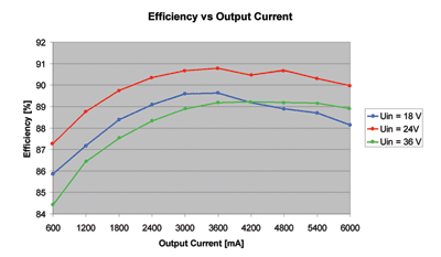
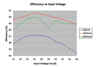
With the help of the above formulas, the maximum allowable ambient temperature for a given set of operating conditions can be calculated, but it is important to remember that efficiency depends on both the output load and the input voltage (see Figs. 1 and 2 ). The formulas also demonstrate that case temperature is not the same as operating temperature.

Fig. 1. Efficiency vs. load current at minimum, nominal and maximum input voltage.

Fig. 2. Efficiency vs. input voltage at minimum, 50% and 100% load.
If the thermal dissipation calculations reveal that the dc/dc module will overheat at the desired ambient operating temperature, then there are still a number of options available to reach a solution.
One option is to derate the converter, that is, use a higher-power converter running at less than full load. The derating diagrams in the datasheets define the maximum load at any given temperature within the operating temperature range.
The derating curves are in reality not so linear as they are declared in most datasheets. However, reliable manufacturers will always err on the safe side so that the values given can be safely relied on in practice.
If the converter has a plastic case, then the next largest case size with the same power rating could be chosen to increase the available surface area. However, care must be taken not to compromise on efficiency otherwise no net gain will be made.
If the converter has a metal case, then adding a heat sink is can be very effective, particularly in conjunction with a forced-air cooling system.
If a heat sink is used with fan cooling, then the thermal resistance equation becomes:
RTHcase-ambient = RTHcase-HS + RTHHS-ambient
where:
RTHcase-ambient Thermal impedance from the case to the ambient surroundings
RTHcase-HS Thermal impedance from the case to the heat sink
RTHHS-ambient Thermal impedance from the heat sink to ambient
The value of RTHHS-ambient incorporates the thermal resistance of the heat sink as well as the thermal resistance of any thermally conductive paste or silicon pads used for a better thermal contact to the case. If these aids are not applied, then a value of about 0.2 K/W must be added to the thermal resistance of the heat sink alone. When establishing the value of RTHHS-ambient it is also necessary to know how much air is being blown across the heat-sink fins. These values are most often given in linear feet per minute (lfm) and declared by the fan manufacturer. The conversion to m/s is 100 lfm = 0.5 m/s.
This has been a basic overview for all users confronted with a thermal management issue, but it has covered the main points that need to be considered. If however, the results of your calculations or measurements are borderline, then the issue must be examined in more depth.
So, for example, there is a difference in thermal performance between vertically and horizontally mounted modules, between static air and freely convecting air and with air at low atmospheric pressures. However, investigating all of these factors would take up too much space in this article. ■
Advertisement
Learn more about Recom Power


