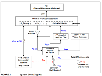
Figure 2 shows the system block diagram of the solution. The difference amplifier uses MCP6V01 auto-zeroed op amp to amplify the thermocouple’s EMF voltage.
The CVREF is an internal comparator voltage reference of PIC18F2550, which is a 16-tap resistor ladder network that provides a selectable reference voltage. It has low accuracy and high variable output resistance. The buffer amplifier eliminates the output impedance loading effect and produces the voltage VSHIFT that shifts the VOUT1 .
The VSHIFT is brought back into the PIC18F2550, sampled and calibrated by the internal ADC, then used to adjust measured VOUT1 , so that the temperature range is segmented into 16 smaller ranges. This gives a greater range (-100°C to +1000°C) and better accuracy.
The MCP1541 provides a reference voltage of 4.1V which references the PIC18F2550’s internal 10-bit ADC. The 2nd order RC low-pass filter reduces noise and aliasing at the ADC input.
The MCP9800 senses temperature at the thermocouple connector, or cold-junction. It should be located as close as possible to the connector on the PCB. This measurement is used to perform cold junction compensation for the thermocouple measurement.
The Thermal Management Software is used to perform data acquisition to show the real-time temperature data.
Download full block diagram below
Advertisement

Learn more about Microchip Technology


