BY WIL FLORENTINO
Senior Manager, Industrial Automation Segment
Renesas Electronics America Inc.
www.renesas.com
Embedded engineers designing modern industrial systems for advanced robotics, automated machines, and motion systems require putting together many elements to build an industrial servo drive. That includes real-time, deterministic operation; high computational architecture and enough memory for the application; and industrial network connectivity for distributed control.
Unfortunately, these disparate subsystems are usually kludged together from past experiences in spinning a simple servo motor, attending seminars on industrial Ethernet protocol programming, or taking a summer class on control theory and algorithms. Thinking through how these elements really interconnect can result in a more efficient, multi-channel motion-control solution that is scalable for different applications.
Here are three design case studies on how to simplify servo drive development, addressing challenges around managing multiple industrial Ethernet protocols. That includes Profinet, EtherCAT, and Ethernet/IP.
A conventional servo drive solution (Fig. 1 ) contains distinct components that have to work in a best case “real-time” operation to spin a motor. 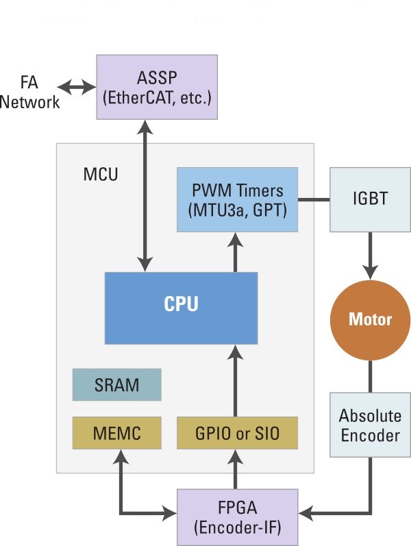 Fig. 1: A conventional drive solution.
Processor subsystem for real time
The contemporary real-time embedded systems used for servo drives need high-performance architectures to implement field-oriented control algorithms that use high-carrier frequencies. When this is combined with position loop and used with trajectory generation, the computational load increases, especially if the second axis of motion is added to the system.
Many current microcontroller solutions run out of processor bandwidth in this application alone. The idea of using a microprocessor (MPU) or microcontroller (MCU) with more processor bandwidth is the typical solution.
The challenge here is that as the CPU clock goes higher and the memory system cannot keep up, we require either wait states or high-speed cache memory. Cache memory is problematic in a hard real-time system because it lacks the determinism needed for a bounded execution time.
A typical application will use more program and data than will fit in the cache. If there is a cache miss, the code or data must be loaded from slower memory, and this causes execution times to vary. Typical MPU cores also lack a vectored interrupt controller, which requires the software to do more processing to find the interrupt source and dispatch the proper interrupt service routine.
The combination of the effects of cache memory and the interrupt controller results in non-deterministic behavior and unbound execution time if multiple interrupts occur.
An architecture designed for real time, for instance, with a nested vector interrupt controller and tightly coupled memory (TCM), assures high-availability operation (Fig. 2 ). The vectored interrupt controller will dispatch to the proper interrupt handler directly through the vector table via hardware, which minimizes the interrupt latency. 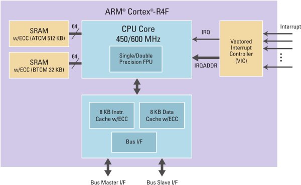 Fig. 2: A view of a real-time architecture featuring TCM and vector interrupt controller.
The TCM is attached directly to the core at the same memory hierarchy as cache memory. The TCM is a simple SRAM with no tags like the cache, so it’s small and efficient to implement. Next, a built-in double-precision floating-point unit (FPU) acts as a math coprocessor to the CPU and simplifies math operation.
Another benefit of a real-time processor subsystem is jitter reduction. Because the motion involves very high-speed calculation, the accuracy of the position control is critical when dealing with micron-level resolution. For example, if a servo drive is operating at 10 m/s and the position is captured with a timing offset (interrupt latency plus jitter) of 2 μs, the resulting position error would be 0.02 mm.
Although this may not seem significant, propagating this position error in time will result in production errors and scrapped units.
Industrial Ethernet accelerator in hardware
Industrial Ethernet requires efficient packet handling to enable communication that is as deterministic as possible. The problem with the typical TCP/IP protocol is the inherent latency when TCP checks the delivery of data and retransmits if data is not successfully received.
Traditionally, frames are processed using specific software procedures to handle the Ethernet header and data. It obviously takes time and could be seen as “overhead” for the CPU, therefore affecting the CPU throughput.
The industrial Ethernet protocols run at about 100 Mbps and are UDP-based, so there is no room for packet loss, especially in motion-control systems. Many MCUs that feature 100 Mbps and media-independent interfaces (MIIs) cannot process the frame payload without the risk of indeterminate jitter because it is not optimized for high-speed packet processing.
Because the CPU needs to prioritize the control-loop arithmetic, there could be dropped packets, or worse, a non-synchronized distributed motion system.
If high-speed operations such as encoding/decoding data packets or simple checksums can be implemented in hardware to improve the packet processing and offload the CPU bandwidth for other tasks, it can improve the RTOS operation as well as reduce additional overhead for checksum operation (Fig. 3 ).
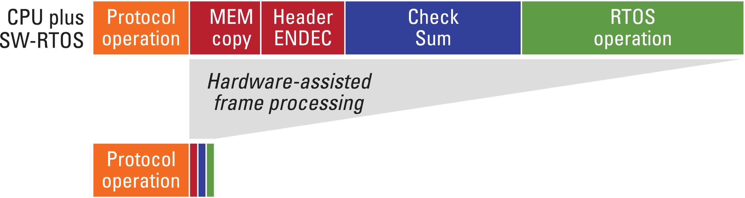
Fig. 3: Hardware-assisted frame processing.
Firmware for real-time control
Firmware operations need to be partitioned in different tasks based on their need for deterministic behavior. 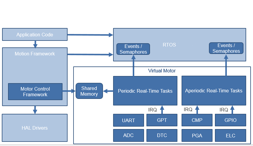 Fig. 4: Motor- and motion-control application architecture.
A firmware architecture built around a Virtual Motor module block (Fig. 4 ) will simplify development. It includes functions that execute deterministic periodic and aperiodic tasks. They interface with the motor-control hardware on one side and with the rest of the firmware modules on the other.
The periodic real-time task is invoked from the interrupt handler of the timer that generates the PWM period. It ensures deterministic timing of the control function calls. And that includes obtaining the current position, executing the position control loop and the current control loop — a.k.a. field-oriented control — generating the duty cycle for the next PWM period, and collecting data for future diagnostics.
The aperiodic real-time task responds to events triggered by external analog or digital signals. The control function evaluates the context to act in the event of current overload or position capture.
The Virtual Motor can recognize different commands providing access to all control parameters and algorithms. The host can obtain information periodically to track the status of each motor and control the execution of motion requests. Alternatively, the host can configure the collection of samples from different variables that can be buffered on the devices and analyzed at a later time.
Then a motor-control framework can be instantiated as a wrapper that uses shared memory to interact with the Virtual Motor and other peripherals to communicate with the host computer. The Virtual Motor is also integrated with an RTOS by triggering semaphores that can coordinate the operation of application-specific threads.
Real-time processor: key takeaways
Designing your own servo drive can get complicated, given the need to accommodate real-time control, connectivity, and a firmware architecture that is scalable for different applications or product variants.
Using a real-time processor core allows a more deterministic operation and reduces jitter. Having the ability to leverage hardware IP to accelerate and improve networking throughput or a programmable block to support different encoders eases the management of distributed motion and various protocols.
Finally, designing firmware that can support different types of applications will help to further simplify the development process. Approaching servo drive design with these factors in mind will help get you up and running in building your own servo motor drive controller.
Advertisement
Learn more about Renesas Electronics America


