The PROFIBUS-DP (Distributed Peripherals) fieldbus standard has been around for over two decades and, yet, physical layer requirements can still be unclear, often leading to confusion in transceiver definitions. However, any ambiguity clearly didn’t stop PROFIBUS from becoming a very successful fieldbus solution, with over 50 million devices installed worldwide. As new systems are deployed, it’s important for design engineers to know they are using transceivers designed to the most up-to-date and accurate interpretation of the PROFIBUS-DP standard.
PROFIBUS-DP (Distributed Peripherals) basics
The faster, simpler PROFIBUS-DP standard was born in 1993 from the slower, more complex PROFIBUS FMS (Fieldbus Message Specification) parent standard. PROFIBUS-DP also has a younger, less popular sibling or derivative standard, PROFIBUS-PA (Process Automation), which uses Manchester Bus Powered (MBP) transmission with power over the bus, making it well suited for intrinsic safety applications in hazardous environments. But PROFIBUS-DP is the most widely used version of PROFIBUS today because of its plug-and-play nature, flexibility, and cost-effectiveness. From the management of sensors and actuators in an industrial plant to communication with flow meters in a rail yard, and various robotics applications, PROFIBUS-DP decentralizes I/O cards (masters) from controllers and brings them closer to sensors and actuators (slaves), resulting in numerous installation and operational benefits.
PROFIBUS-DP can communicate over a variety of media, including copper wires, fiber optics, and even air in an infrared communicator. By far, the most commonly used media for bit transmission (layer 1 of the ISO/OSI model) by PROFIBUS-DP masters and slaves is twisted pair using RS485 transceivers. This isn’t surprising, considering RS485’s high-speed differential signaling and robust communication between multiple devices over long distances in noisy environments. Multiple masters, such as PLCs (programmable logic controllers), can connect to 30 slaves per segment in a linear topology. Networks can be expanded to 124 slaves with the use of hubs (parallel segments) or repeaters (serial segments). Segments must be terminated at both ends using active termination. All slaves can be hot-swapped into the bus, and their position does not matter because each slave is assigned a unique network address.
95% RS485, 5% confusion
PROFIBUS-DP adopted much of the TIA/EIA-485-A RS485 standard, but did make a few changes that can be accidentally overlooked due to larger system issues. As a result, contrary to popular belief, not all RS485 transceivers and cables are suitable for PROFIBUS-DP networks. Differences in cabling, termination, signal names, and driver requirements do exist; being too quick to dismiss these differences could easily cost you the performance (or worse, the certification) of your master or slave device.
While the RS485 standard does not specify cabling requirements, 120-Ω shielded twisted pair has become the normal recommendation. PROFIBUS-DP, however, recommends 150-Ω shielded twisted pair. Unfortunately, 120 Ω cannot be approximated as 150 Ω and this small difference in cable impedance actually necessitates the use of different cables. PROFIBUS-DP also specifies a maximum cable length that depends on which one of 10 baud rate “steps” is used, ranging from 1,200 m at 9.6 kbits/s to 100 m at 12 Mbits/s.
Of course, with different cable impedance requirements, comes different termination requirements. To minimize signal reflections, RS485 installations typically use a single 120-Ω termination resistor at both ends of the bus, whereas PROFIBUS-DP recommends a 171-Ω termination network at both ends of the bus. Wait, was that a typo? PROFIBUS-DP recommends 171-Ω, thereby not matching the 150-Ω characteristic impedance of the recommended cable? Absolutely. Fig. 1 shows how the cable and termination network used for PROFIBUS-DP is different from RS485. You can see that two 390-Ω bus biasing resistors are used with the 220-Ω termination resistor; the differential resistance being 171 Ω. This is obviously not a perfect match for the 150-Ω cable, resulting in a slightly underdamped network. However, don’t worry, as this reveals itself as only a small bump or increase in signal voltage at the receiving end of the cable, lasting twice as long as the cable propagation delay.
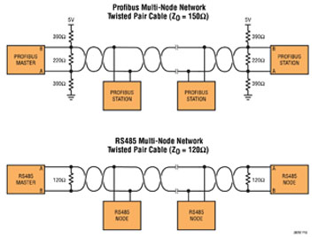
Fig. 1: Cable, termination, and pin differences in RS485 and PROFIBUS-DP networks.
If the cable/termination mismatch were not enough, then the naming of the bus pins on PROFIBUS transceivers should further break your expectations. You may have noticed the opposite pin names used in Fig. 1 . In most general-purpose RS485 transceivers, pin A is the non-inverting receiver input (and non-inverting driver output) and pin B the inverting, relative to the receiver output and driver input. However, the PROFIBUS standard describes the bus polarity in such a way that pins B and A are exactly the opposite of this. Why the inconsistency? The original TIA/EIA-485-A standard is not explicit in its definition of the bus polarity relative to the logic signal function, so RS485 IC designers have almost always interpreted the specification one way while others have interpreted it the other way. What that means for you, especially if you have both RS485 and PROFIBUS-DP projects, is you must pay close attention when mapping transceiver bus pins to connectors.
Based on the number of ill-defined transceivers available off-the-shelf, differential driver output voltage (VOD ) is perhaps the most misinterpreted or ignored specification in PROFIBUS-DP’s physical layer. RS485 specifies that the VOD between the A and B lines shall be 1.5 to 5 V, peak differential, measured at the driver terminals with a 54-Ω resistor between A and B. PROFIBUS-DP specifies that the VOD shall be 4 to 7 V, peak-to-peak differential, measured at the far end of the cable, with termination at each end.
A common misunderstanding is that if an RS485 driver simply develops more than 2.1 V across a 54-Ω load, then it will meet PROFIBUS-DP’s requirements when used with a PROFIBUS-DP termination network. However, this is not always true. The strength of an RS485 driver can be too high and exceed the 7-VPP PROFIBUS-DP limit. Be wary of the all too common “PROFIBUS” compatible RS485 transceiver that only specifies a VOD minimum value (i.e., 2.1 V) without a maximum value. The best way to ensure PROFIBUS-DP VOD compliance is to test the transceiver with a PROFIBUS load.
Fig. 2 shows how the LTC2877 Rugged PROFIBUS RS485 Transceiver is tested with a PROFIBUS-DP load and some series resistance to simulate cable losses, where the VOD (blue curve) is generated from measurements taken at the “end of the cable” (A’ and B’) to ensure the PROFIBUS-DP specification is truly met. The LTC2877 is also fully tested with RS485 loads to ensure VOD compatibility with both standards.
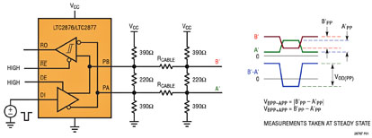
Fig. 2: Testing the LTC2877 differential output voltage (VOD) using a PROFIBUS-DP load.
Protecting PROFIBUS-DP
The TIA/EIA-485-A standard specifies very little when it comes to combating noise, faults, ESD, transients (Electrical Fast Transients), or surges, leaving it open for transceiver manufacturers and designers to implement their own electrical protection. While protection requirements differ application to application, some transceivers, including the LTC2877 shown in Fig. 3 , can cover all market requirements with high levels of protection.
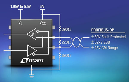
Fig. 3: LTC2877 transceiver provides multiple levels of protection.
The TIE/EIA-485-A standard specifies that ground shifts between two devices on a network can be as large as –7 to +12 V. However, many PROFIBUS-DP installations can encounter voltages much greater than this, which can cause critical damage to a PROFIBUS-DP transceiver. PROFIBUS is often used in 24-V systems, where shorting a “standard” RS485 device to 24 V can be fatal. The designer should require a receiver with an extended common mode range of –25 to +25 V. Replacing the usual PROFIBUS-DP transceiver with the ±60-V protected LTC2877 can eliminate field failures due to overvoltage faults without costly external protection. Because PROFIBUS-DP transceivers are literally a system’s first line of defense, they need to be able to protect themselves against various levels of ESD strikes. Some PROFIBUS transceivers are protected to 15-kV ESD protection on their bus pins while unpowered; others, like the LTC2877, provide ±26-kV HBM ESD protection with respect to ground or either of the supplies without latch-up or damage, unpowered or powered, and in any mode of operation. Furthermore, the bus pins are protected against a ±52-kV strike to ground surge when unpowered.
Another form of electrical overstress is EFTs, which, according to the IEC 61000-4-4 EFT standard, are bursts of high voltage spikes lasting 60 seconds. This type of overstress is usually a result of arcing contacts in switches and relays, common in industrial environments in which electromechanical switches are used to connect and disconnect inductive loads. They should be sure that the transceiver selected meets the highest level of IEC 61000-4-4 severity, which is level 4, equating to an open-circuit voltage of 2 kV on the bus pins.
Perhaps the most severe form of electrical overstress is the surge Mother Nature delivers in the form of lightning. It’s no surprise, then, that tiny transceiver ICs, like the LTC2877, do not possess inherent protection against electrical surges of this magnitude. Instead, external surge protection components, including MOVs, TVS diodes, TSPDs (thyristor surge-protection devices) and GDTs (gas-discharge tubes), are typically used in PROFIBUS-DP systems that are exposed in any way to the elements. The LTC2877 won’t fare well against lightning strikes solo, but its high ±60-V pin rating makes it easy to find external protection components capable of providing this level of protection.
Advertisement
Learn more about Linear Technology


