Reducing clock jitter sensitivity in digital audio systems depends on how DAC designs deal with jitter
BY LARRY GADDY and GREGG ROUSE
AKM Semiconductor, San Jose, CA
http://www.akm.com
The effect of clock jitter on digital audio performance is a subject that is never short of diverse opinions. It is one of those “conventional wisdom” topics, where everyone knows it is inherently bad, but the devil is in the details. Understanding how different digital-to-audio converter architectures deal with jitter can go a long way toward determining the best return on jitter-reduction techniques.
Clock jitter in a digital audio system is classically defined as phase modulation on the master sample clock. This clock is used to trigger sampling in the delta-sigma DAC’s modulator, and jitter can have large effects on the audio quality due to incorrect sample timing. Master clock jitter results in nonlinear distortion of the input signal, manifested as an increase in the noise floor or total harmonic distortion, depending upon the type of jitter:
V = A * sin (2πft)
dV/dt = A * 2πf * cos(2πft)
dV/dt(max) = A * 2πf
Tj = dt = dV/(2πft)
When dV = THD = 0.003% (90 dB)
Tj = 9.5 ns (f = 1 kHz)
Tj = 0.95 ns (f = 10 kHz)
When small signal (dV = 0.03%)
Tj = 95 ns (f = 1 kHz)
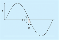
Figure 1 illustrates the relationship between distortion and jitter. In order to meet the maximum distortion specification of – 90 dB, the clock jitter must be less than 0.95 ns for a 10-kHz input frequency. Smaller amplitudes are less sensitive to jitter, so some manufactures reduce the output swing of the DAC to improve overall jitter sensitivity. However, this can be very detrimental to SNR performance due to coupling of the jitter noise into the noise floor of the DAC. Every device datasheet includes a reference to improved jitter sensitivity, but this may be as simple as increasing the master clock, and using a clock divider to attenuate the jitter.

Fig. 1. Relationship between distortion and jitter. Types of jitter
There are two primary types of jitter: random and periodic. Random jitter results when the clock generator’s output is altered in a random fashion, which essentially adds noise to the signal. Random jitter can be rejected by the DAC architecture, reducing overall sensitivity. Periodic jitter occurs at regular intervals, which results in audio sidebands or tones. Periodic jitter is difficult to reject, and in most cases, the clock source must be improved in order to eliminate tones caused by periodic jitter. Digital PLLs often produce periodic jitter, so in audio systems, it is best to use analog PLLs. Random jitter usually contributes to an increase in the noise floor (reducing SNR and dynamic range), while periodic jitter increases tones (reducing THD performance).
Switched-capacitor filter DACs reduce jitter sensitivity
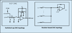
Modern delta-sigma audio DACs have two basic DAC architectures: switched-capacitor and resistor-based. Figure 2 illustrates the basic circuit diagram for these two differing architectures. For the switched-cap filter architecture, the output voltage is equal to the input voltage multiplied by the ratio of CS /CI . The output voltage settles to 0.01% within 100 ns. The sampling time is equal to one-half the CF switching speed, which is 160 ns. When the clock jitter is less than 60 ns (easily obtained from most audio clock sources), VOUT is constant. The performance of a converter using this architecture is relatively independent of clock jitter.

Fig. 2. For the switched-cap filter architecture, the output voltage is equal to the input voltage multiplied by the ratio of CS /CI , while for the resistor architecture, VOUT is derived from the ratio of the feedback and input resistors.
For the resistor architecture, VOUT is derived from the ratio of the feedback and input resistors. Any clock jitter present on the input resistor switches directly translates to VOUT , so this architecture is highly sensitive to clock jitter.
Effect of jitter on audio DAC performance
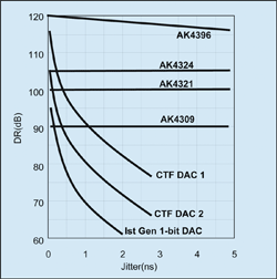
Figure 3 illustrates the effect of jitter on dynamic range of several DAC’s. At the bottom of the chart is a first-generation 1-bit DAC. Any jitter rapidly degrades the performance of this older architecture. Next are two examples of resistor topology DACs, nominally specified with SNR of 105 and 110 dB, respectively. These DACs also degrade rapidly with increased jitter, since the jitter has a direct effect on VOUT errors.

Fig. 3. The effect of jitter on dynamic range decreases with each succeeding generation of DAC.
The top four examples are various generations of AKM switched-capacitor DACs. The AK4309 was a first-generation single-bit DAC, while the AK4396 is a fourth-generation multibit SCF DAC. Only the very-high-performance DAC shows any sensitivity to jitter, which is actually caused by noise coupling. With very small noise floors (120 dB for the AK4396), random noise from clock jitter can couple into the output circuit. For lower-performance DACs, the noise floor is already higher than the contribution from jitter, so no effect is observed.
Switched capacitor advantage
In addition to improving jitter sensitivity, the switched-capacitor filter architecture provides other benefits that improve audio performance and reduce cost. In a pure 1-bit system, the output amplifier must switch between the rails. Given the high speed of the modulator, this requires extremely high slew rates, as well as matching between the rise and fall time. The bandwidth of the amplifier must be very large as well—these constraints do not translate well into small-geometry low-cost processes. The switched-capacitor DAC architecture is designed to deliver superior performance at low cost, with inherent resistance to clock jitter.
AKM Semiconductor (AKMS) is a wholly owned subsidiary of Asahi Kasei Microsystems Co, (AKM), Tokyo, Japan. Located in San Jose, CA, AKMS offers sales, marketing, and design support for North American customers. AKMS designs and manufactures CMOS mixed-signal ICs for applications including audio, multimedia, data storage, and telecommunications.
Advertisement
Learn more about AKM Semiconductor


