Understanding current switching’s special needs
Unless signal differences are taken into account, they can degrade signal integrity and affect total test system performance
BY DALE CIGOY
Keithley Instruments
Cleveland, OH
http://www.keithley.com
The differences among the types of signals that a test system’s switching hardware must handle are not always well understood. But if these differences are not taken into account in switch system design, they can degrade signal integrity and affect overall test system performance.
When designing a measurement system, selection of the switch is as critical as the selection of system instrumentation or the design of the test interface. The intended application must be thoroughly considered, and the switch selected must meet the requirements of the application. Careful attention to detail and to the basic principles of measurement can help ensure greater system accuracy and performance.

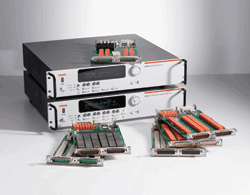
The Series 3700 switch system/multimeter family with model 3740 32-channel isolated switch cards.
Voltage vs. current switching
Voltage sources can usually provide a compliance current up to the programmed voltage. As a result, the typical default condition of a voltage switch is open (in other words, drawing very little current or having high impedance).
Current switching, however, usually requires the default configuration to be a complete circuit. This means the current needs a complete path until switched. Typically, the switching component (that is, the relay) is a normally closed relay, or the HI and LO terminals are shorted in the default condition.
A variety of switching topologies are suitable for use in current switching applications: scanner, multiplex, and matrix switching. The scan configuration or scanner is the simplest arrangement of relays in a switch system. It can be thought of as a multiple position selector switch.
Like the scan configuration, multiplex switching can be used to connect one instrument to multiple devices (1:N) or to connect multiple instruments to a single device (N:1). However, the multiplex configuration is much more flexible than the scan configuration. Unlike the scan configuration, multiplex switching enables making multiple simultaneous connections and also permits either sequential or nonsequential switch closures.
The matrix switch configuration is the most versatile because it can connect multiple inputs to multiple outputs. A matrix is useful when connections must be made between several signal sources and a multi-pin device, such as an integrated circuit or a resistor network.
Typical current concerns
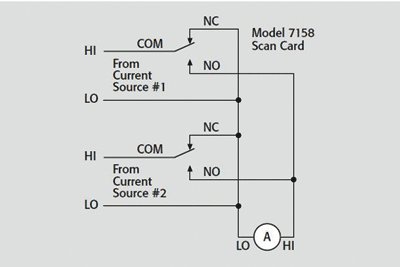
Most current measurement applications demand that all current paths be continuous, even when a particular current signal is not connected to the ammeter. To accomplish this, switch cards designed for current switching often use SPDT or Form C relays (see Fig. 1 ).

Fig. 1. Form C relays can be used to switch multiple current sources.
As illustrated in Fig. 1 , when a channel is in an open state (that is, not connected to the output), signal HI is connected to signal LO through the normally closed (NC) contact. In this case, only signal HI is switched. Signal LO is hard-wired to the ammeter and to all other signal LOs. This is typically the case when testing components with relatively low currents (for example, 1 μA). When a channel is selected, the current source is connected to the ammeter through the normally open (NO) contact.
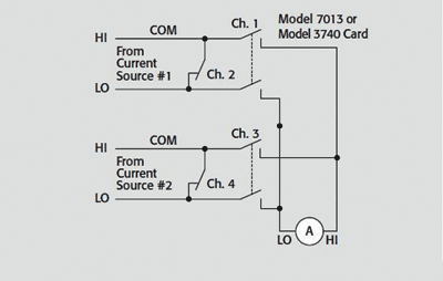
Note that the current will be interrupted briefly when the Form C relay is actuated. This could cause problems when used with high-speed logic or other circuits sensitive to a momentary break in the current flow. Such a problem can be overcome by using a switch card such as those used with the Series 3700 switch system/multimeter with a pair of Form A isolated switches to provide a make-before-break connection (see Fig. 2 ).

Fig. 2. Form A relays provide uninterrupted current switching.
High-current considerations
When designing a switching circuit for high current (> 1 A), pay particular attention to the maximum current, maximum voltage, and VA specifications of the switch cards and relays. Also, it is important to choose a switch card or relay with low contact resistance to avoid excessive heating, which can cause contacts to weld together and thereby lead to contact failure. Contact heating is caused by I2 R power dissipation.
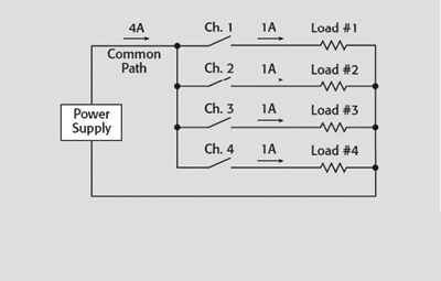
High-current switching can be used for either switching a power supply to multiple loads or for switching an ammeter to multiple sources. When a power supply is switched to multiple loads using a multiplexer scanner card (see Fig. 3 ), the power supply will output 1 A to each of four loads. This does not present a problem when only one channel is closed at a time, but when all four channels are closed, the power supply will output 4 A through the common path.
Unfortunately, even though the maximum current of a particular channel is specified at 1 A, the common path on the switch card may not be able to tolerate 4 A. This is not usually specified for a switch card, but the limitation is usually a function of the trace width and connector ratings. One way to avoid this problem is to use a switch card with independent (isolated) relays and to make connections with wires rated to carry the total current.

Fig. 3. A multiplexer can switch a power supply to multiple loads.
Low-current considerations
When switching currents of 1 μA or less, special techniques must be used to minimize sources of interference such as offset currents, leakage currents, electrostatic interference, triboelectric currents, and electromechanical currents. The interference might come from the switch card itself, the connecting cables, or the test fixturing.
Offset currents are spurious currents generated by a switching card even though no signals are applied. They are usually caused by galvanic sources on the switch card. Offset current is especially significant when measuring low currents if the magnitude of the offset is comparable to that of the current being measured.
Leakage current is an error current that flows through insulators when a voltage is applied. It can be found on the switch card, in cabling, and in test fixtures. Even high-resistance paths between low-current conductors and nearby voltage sources can generate significant leakage currents.
To reduce these effects, always use a switch card with high channel isolation and use the guard capability of the measurement instrument. Another method to help reduce leakage current is to keep the switch card clean. Dirt, body oils, and the like will create a lower-resistance path and allow leakage currents to flow.
To reduce leakage currents in the text fixturing, always use good quality insulators such as Teflon and polyethylene; avoid materials such as nylon and phenolics, which can absorb moisture, affecting their insulating performance.
Shielding is required because high-impedance circuitry is susceptible to picking up spurious radiated noise. Relay contacts should be shielded from the coil to minimize induced noise from the relay power supply. The device under test and interconnect cabling should also be shielded to prevent noise pickup. All shields should be connected to circuit LO.
Triboelectric currents are generated by charges created by friction between a conductor and an insulator, such as between the conductor and the insulation of a coaxial cable. The friction can be reduced by using special low-noise cables with conductive coating (such as graphite) and by securing the interconnect cabling to minimize movement.
Electrochemical currents are generated by galvanic battery action that results from contamination and humidity. Cleansing joints and surfaces thoroughly to remove electrolytic residues (which include PC etchants, body salts, and processing chemicals) will minimize these parasitic battery effects.
Settling time
When a relay opens or closes, a charge transfer on the order of picocoulombs occurs, which causes a current pulse in the circuit. This charge transfer is due to the mechanical release or closure of the contacts, the contact-to-coil capacitance, and the stray capacitance between signal and relay drive lines. After a relay is closed, it is important to allow sufficient settling time before taking a measurement. This can be as long as several seconds, depending on the relay.
If a step voltage is applied to the circuit, a transient current is generated. This current will gradually decay to a steady-state value. The time needed to reach the steady value (or settling time) can be used to determine the proper measurement-delay time.
Cold, hot, and safe
The term “cold switching” indicates that a switch is activated with no signal applied. Therefore, no current will flow when the switch is closed and no current will be interrupted when the switch is opened. When hot switching, voltage is present and current will flow the instant the contacts close. When the switch is opened, this current will be interrupted and can cause arcing.
Cold switching lets power be applied to the device under test in a controlled manner. Its primary advantage is longer switch life than with hot switching. Cold switching also eliminates arcing at the relay contacts and any RFI it might cause.
Hot switching might be necessary if close control must be exercised in the period between the application of power and the making of the measurement. For example, hot switching is typically used where digital logic is involved, because devices might change state if power is interrupted even for a moment.
With relatively large relays, hot switching should also be performed every so often to ensure good contact closure. The connection might not be reliable without the “wetting” action produced by current flow through the contacts.
Many electrical test systems can produce hazardous levels of power. These high power levels make operator protection a priority. Some protection methods include:
Designing test fixtures that prevent operator contact with hazardous circuits.Double-insulating all electrical connections that an operator could touch.Using high-reliability fail-safe interlock switches that disconnect power sources when a test fixture is opened.Providing proper training to all users so that they understand potential hazards and know how to protect themselves from injury. ■
Advertisement
Learn more about Keithley Instruments


