Understanding features and specs of today’s LDOs
Consider the input power source, the loading requirements, and the transient response before selecting an LDO for a system
BY KEVIN TRETTER
Microchip Technology, Chandler, AZ
http://www.microchip.com
As today’s electronic devices become more and more complex, the need to provide a wide range of regulated voltage supplies continues to increase. Additionally, battery-powered electronic devices must contend with the limited voltage/current provided by the battery, making the task of providing several regulated voltages even more complicated.
The use of low dropout regulators (LDOs) is popular for a wide variety of applications, including battery-powered electronic devices. However, it is critical that the designer understand the features and specifications of the LDO, and how these specifications affect the overall system.
Overview of LDO architecture
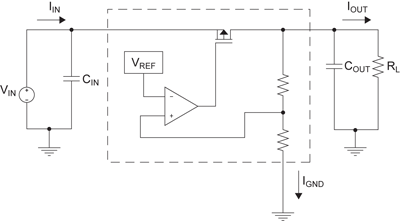
A LDO uses a voltage-controlled current source to create a given output voltage. LDOs consist of a bandgap reference, an amplifier, a pass transistor and a feedback network (see Fig. 1). The pass transistor, typically an n-channel or p-channel FET, functions as a variable resistor in order to regulate the output voltage. This output voltage is compared to the band gap reference, and the amplifier drives the pass transistor accordingly to equalize the voltage on its inputs.

Fig. 1. Basic LDO architecture
Dropout voltage
Since the LDO architecture relies on adjusting a resistive element to create a given output voltage, a LDO (or any linear regulator) can only create an output voltage that is lower than the input voltage. The minimum required differential voltage between the input and the output in order for the output to maintain regulation is called the dropout voltage. Since a LDO uses only a single FET transistor as the pass element, it has a lower dropout voltage than the other linear-regulator topologies; hence the name low-dropout regulator, or LDO.
Dropout voltage becomes a critical specification in battery-powered applications where the LDO is used to regulate the battery voltage. For example, consider an application that is powered from a single lithium-ion (Li-Ion) cell. A Li-ion cell has an open-circuit voltage of approximately 3.6 V when fully charged, and will decrease in voltage to approximately 2.7 V when fully depleted. In this example, an LDO is used to regulate this battery voltage to 2.5 V, to power the rest of the system. If the LDO has a dropout voltage of 200 mV or less, the output of the LDO will remain regulated until the battery is completely used. However, if the LDO has a dropout voltage of 500 mV, then the output will fall out of regulation when the battery voltage drops to 3 V. In this case, the battery cannot be fully depleted and therefore battery life is negatively affected.
Line regulation
Another common specification for LDOs is line regulation. This specification indicates how well the device regulates the output voltage under a varying input voltage. Line regulation is typically specified as a percentage change in the output voltage for a 1V change in the input voltage (%/V). It is important to note that line regulation is a dc, or steady-state, parameter. Therefore, any output-voltage transients that result from a change in the input voltage are ignored.
In the example used above to discuss dropout voltage, a LDO provided a regulated 2.5V output from a single Li-ion battery. In this example, the input voltage to the LDO changes over time as the Li-ion battery cell becomes depleted. Therefore, the output voltage of the LDO, although nominally 2.5V, will vary as the battery voltage varies. The degree of this variation is a function of the LDO’s line-regulation specification.
Line regulation can also be a critical factor for systems that support multiple supply sources, such as an ac/dc converter with a battery backup. In this case, the main power supply may be a 12V supply coming from the ac/dc converter, but if power is lost, the system switches to a battery backup, which may be running at 9 V. How a LDO reacts to this sudden step in the input voltage can be critical. If the output of the LDO changes significantly, this could cause other system failures.
Load regulation
While line regulation accounts for changes in the input voltage to the LDO, load regulation accounts for changes in the output loading of the LDO. By definition, load regulation is the ability of the LDO to maintain a constant output voltage under varying current-load conditions. This specification is typically shown in a datasheet as a percentage change in the output voltage of an LDO per a given change in load current.
In applications where the current loading will change significantly, load regulation becomes an important specification for the LDO. For example, let’s consider a system that implements a LDO to provide a regulated power supply to a microcontroller. The microcontroller could have multiple states of operation—perhaps a shutdown or sleep mode—along with various levels of activity. The current draw of such a device can change rapidly as the microcontroller goes from one state to the next, and any voltage glitches on the power-supply rail could adversely affect the microcontroller. Therefore, being able to provide a steady output voltage under various current loads becomes critical in selecting the proper LDO.
Power-good indicator
Outside of the basic operation of a linear regulator, some LDOs such as Microchip’s MCP1825, offer additional features such as a power-good indicator. This feature provides a logic output that indicates when the output of the LDO is stable and within regulation. Typically, this output pin includes some built-in hysteresis to avoid false triggers caused by noise or other phenomenon.

Fig. 2. LDO with power good
A power-good indicator can be very useful when implementing a LDO to power a sensitive device that requires a very clean start-up voltage. In this case, the LDO’s output can remain disconnected from the load until the Power-Good indicator becomes active. At that time, the system can connect the output of the LDO to the load, ensuring a clean, stable power supply that will not cause any issues resulting from a slow transient on the power supply.
Overtemperature protection
Another useful feature found on certain LDOs is overtemperature protection. As with all silicon integrated circuits, there is a maximum temperature limit for the silicon, typically called the maximum junction temperature, around 150C. Beyond the maximum junction temperature, the silicon can become permanently damaged. Some LDOs, including the MCP1825, implement over-temperature protection circuitry that monitors the internal junction temperature of the silicon. If it reaches the maximum junction temperature (150C for the MCP1825), the output of the LDO will shutdown until the junction temperature drops to an acceptable level. This prevents permanent damage to the integrated circuit from extreme temperatures.
At first glance, low dropout linear regulators appear to be very straightforward and simple to design into a system. For the most part this is true, being one of the advantages of this type of dc/dc converter. However, the system designer must be aware of the various specifications of the LDO and how these specifications affect the overall system design. When selecting the proper LDO for a given application, the system designer must consider the input power source, the loading requirements, and how the transient response of the LDO will affect the rest of the circuitry in the system. ■
Advertisement
Learn more about Microchip Technology


