BY TIM WHITE
System Architect
ZMDI
www.zmdi.com
SENT (Single Edge Nibble Transmission) is a unique serial interface originally targeted for automotive applications. First adopters are using this interface with sensors used for applications such as throttle position, pressure, mass airflow, and high temperature. The SENT protocol is defined to be output only. For typical safety-critical applications, the sensor data must be output at a constant rate with no bidirectional communications that could cause an interruption. For sensor calibration, a secondary interface is required to communicate with the device.
In normal operation, the part is powered up and the transceiver starts transmitting the SENT data. This is very similar to the use model for an analog output, with one important difference: SENT is not limited to one data parameter per transmission and can easily report multiple pieces of additional information, such as temperature, production codes, diagnostics, or other secondary data.

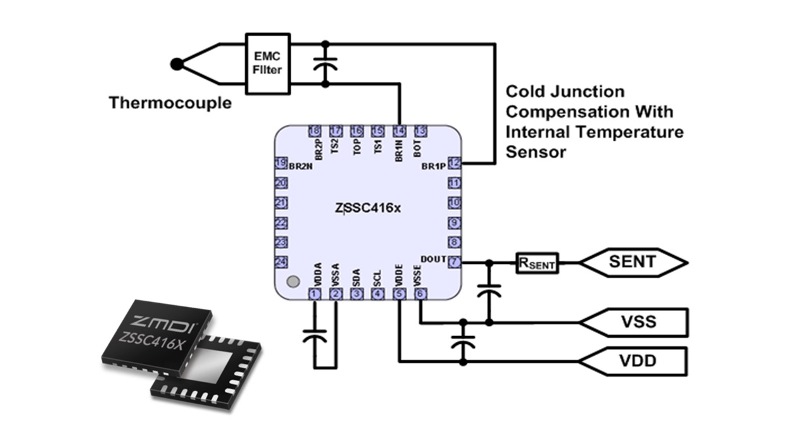
Fig. 1: As seen here, the SENT Interface can simplify connections for sensing, in this case, high temperatures with a thermocouple.
Basic Concepts
The primary data are normally transmitted in what is typically called the “fast channel” with the option to simultaneously send secondary data in the “slow channel.” An example of fast channel transmission (Fig. 2 ) shows two 12-bit data words transmitted in each message frame. Many other options are also possible, such as 16 bits for signal 1 and 8 bits for signal 2.

Fig. 2: This is one example of a typical Fast Channel Message. Many other options are possible.
The basic unit of time for SENT is a tick, and the minimum data unit is a nibble, which communicates 4 bits of data encoded in the combined pulse timing of an initial fixed-width low period followed by a variable-width high period. A synchronization/calibration pulse always starts a message frame and provides a method for measuring the tick time of the SENT output. The message frame usually ends with a CRC/checksum nibble and optional pause pulse.
Tick: unit of time for SENT transmissions. 3µS
Nibble: unit of 4 bits used to transmit data. Within a nibble, the initial logic 0 time is a fixed width of 5 ticks or more, which is followed by logic 1 with a variable duration. The total nibble time encodes 4 bits of data in the measured number of tick units:
- Data value = 0 (decimal) = minimum nibble width of 12 ticks = 0000 (binary)
- Data value = 1 (decimal) = nibble width of 13 ticks = 0001 (binary)
- Data value = 2 (decimal) = nibble width of 14 ticks = 0010 (binary)
- …
- Data value = 14 (decimal) = nibble width of 26 ticks = 1110 (binary)
- Data value = 15 (decimal) = maximum nibble width of 27 ticks = 1111 (binary)
Synchronization/Calibration Pulse: initial sequence used by the receiver, for example an electronic control unit (ECU), to measure the tick timing of the sensor transmission. Divide its duration by 56 to determine the tick time.
Status/Communication Nibble: first nibble after synchronization/calibration pulse. This nibble communicates status and/or slow channel data bits depending on the SENT format.
CRC/Checksum: used for error checking.
Optional Pause Pulse: variable pause pulse, which can be used to maintain a uniform tick count.
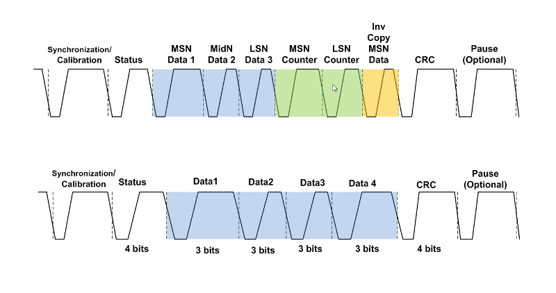
There are two additional fast channel formats: 12-bit Single Secure Message and Fast Channel High Speed. As shown in Fig. 3 , top, a message in the 12-bit Single Secure Message Format transmits one 12-bit data message, an 8-bit incremental counter, and the inverse of the most significant data nibble.

Fig. 3: The 12-bit fast-channel data can be sent in two formats: Single Secure Message Format (top) and Fast Channel High Speed Format (bottom)
In Fig. 3 , bottom, the Fast Channel High Speed Format transmits 12 bits of data in four nibbles. The Fast Channel High Speed Format is unique in that for the four bits encoded in the nibble width, the most significant bit is always logic 0, so only the three least significant bits are the transmitted data.
Slow channel transmission
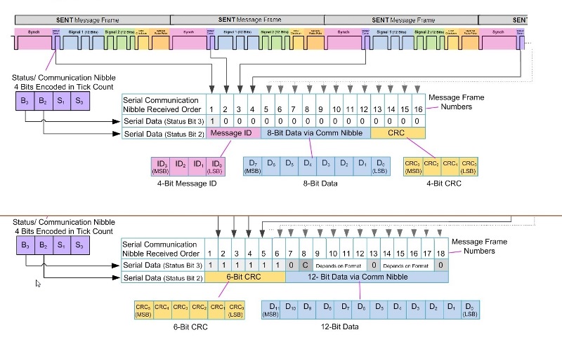
The SENT protocol format that is probably most challenging to understand is slow channel messaging. The basic concept is that slow channel data are sent only two bits at a time, so for each fast channel message frame, the transmitter can also include two bits of slow channel data. These two bits are contained in bit 3 and bit 2 of the status nibble. This is referred to as a “slow” message because it takes many fast channel message frames to complete the transmission of a single value via the slow channel data conveyed in the status nibble of the fast channel data frames. For example, it takes 16 fast channel data frames to transmit only 8 bits of slow channel data. The real power of this feature is that it allows up to 32 slow channel messages per serial message cycle to be transmitted with minimal impact on the primary sensor data.
It is in these slow channel messages that it is possible to continually monitor information such as temperature, diagnostics and production codes, which typically either do not change or change at a slower rate than the sensor data. Each slow channel message is assigned a message ID that is transmitted with the data. The list of message IDs is usually unique to a product and is often defined in the product data sheet or application note.
There are three formats used for sending slow message data: Short Serial Message Format for 8-bit messages and Enhanced Serial Message Format, which can be configured for either 12-bit or 16-bit messages. All three formats support a slow channel CRC checksum sent after the message ID and data.
Short and enhanced formats
With the Short Serial Message Format used for transmitting 8 bits of slow channel data (Fig. 4 , top), bit 3 in the status nibble of the fast channel frame starts at logic 1 and then stays at logic 0 for the next 15 frames. This fixed code of logic 1 followed by 15 logic 0’s helps determine where each slow channel message starts and ends. The message ID, 8-bit slow channel data word, and 4-bit CRC are contained in status bit 2 transmitted one bit at a time via multiple fast channel frames. It requires 16 fast channel message frames to send one Short Serial Message.

Fig. 4: There are two ways to use the slow channel: using 8-bit Short Serial Channel Format (top) or the 12 or 16-bit Enhanced Serial Message Format (bottom).
The Enhanced Serial Message Format (Fig. 4 , bottom) transmits slow channel data in either 12 or 16 bit format. A configuration bit is used to indicate 12 or 16 bit format. The 12-bit format allocates more bits for the message ID. Fig. 4 , bottom shows the 12-bit Enhanced Serial Message Format. For a comparison of the 12- and 16-bit formats, see this sidebar.
Implementation challenges
The challenge with SENT is determining which format is best suited to the application. However, once the format and data set have been selected, it is usually fixed in the design or configured with nonvolatile memory so that the data are continually transmitted on power up. Another key feature of SENT is over-damped rise and fall transitions. This reduces emissions but does set some limitations on the speed.
Tools for decoding the SENT protocol are available on the market including oscilloscopes, software, and microprocessors with SENT decoder hardware included. This interface was first defined in 2007 and now, with SENT version 3.0, the interface is seeing increased interest. Depending on the application, SENT can offer a good alternative to analog output.
Advertisement
Learn more about ZMDI


