BY HAKKI REFAI, Chief Technology Officer, Optecks, www.optecks.com
3-D printing is a disruptive technology that allows a user to synthesize three dimensional objects. Recent printers create object layers by exposing a resin material to ultraviolet light, which cures each new layer onto the previous layer. Digital micromirror devices (DMDs) can pattern ultraviolet light to project the image of each layer into the resin, so an entire layer may be written all at once with high resolution and potentially a high degree of user control. To take full advantage of the DMD capabilities, the user must be able to effectively and smoothly interface with the electronics that control the DMD. The interface must provide proper control signaling for synchronizing the DMD operation with the motor that positions the building platform correctly prior to printing each layer. With the correct software interface, the user can adapt the system and the printer to a wide range of applications that can produce complex parts. For example, a rocket engine that is typically manufactured in pieces can be joined together instead as single components, thereby eliminating weak points at junctions or couplings. Additionally, the software interface and printer can produce new items such as biological test cells or those requiring novel materials that are not producible by any other method. Therefore, new developments in user-system interfaces are needed to help unlock the full power of 3-D printers using TI DLP technology for all interested users.
Optecks has developed a software package called Design23DPrint that provides the user interface and printer interface capabilities that allow the user to quickly and easily create, manipulate, and prepare 3-D models for printing, even at the individual pixel level, either working with existing control software or providing control signals directly to the 3-D printer. The software provides tools and features for importing, manipulating, and editing of 3-D object models obtained from a variety of sources, slicing of the object into layers, and editing of each individual layer on a pixel-by-pixel basis. All controls are presented in an intuitive windows format with menus and dialogue boxes for selecting actions or options. We describe here the operation and features of the software, including the successful integration of the software with a 3-D printer.
The first step
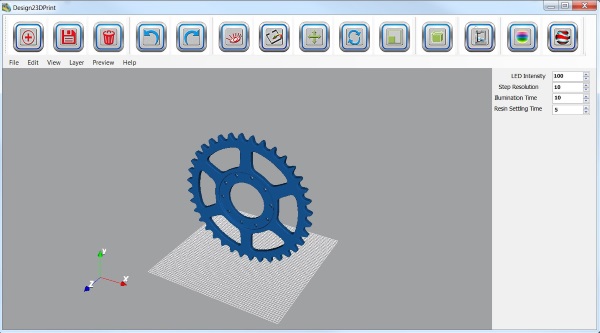
The first step in printing a 3-D object is creating the initial object. The software can import 3D object data in many different formats, including STL, OBJ, and 3DS. The user can import multiple objects simultaneously or duplicate a single object multiple times, and the software will work to ensure that no overlap between objects occurs. Figure 1(a) shows an imported object, along with the main software interface.
Second step
The second step is to edit the object(s) to meet user specifications. The software provides an extensive set of actions to the user through the Edit drop-down menu and shortcut buttons shown at the top of Figure 1(a). A grid spacing can be superimposed on the build platform, and the user can control the size of the grid squares to change the object’s resolution and minimum feature size. The user can rotate, translate, and scale the object with the mouse and menus, view it from several different viewpoints, and zoom in and out. If required, supports can be created and placed manually by the user or the software can autonomously choose the number, location, and other properties of the supports. The software allows printing of both solid and lattice-filled objects, and can perform all operations on multiple objects simultaneously, significantly reducing the editing time.
Third step
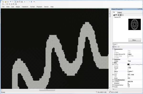
After these editing steps are completed, the third step is to slice the object into the individual layers to be printed. In the first part of this process, the user can specify several different parameters through the layer menu and the editing panel at the right of Figure 1(a). The user can specify the number of layers or the layer thickness, as suits the needs of the printing project. Once all layering parameters have been selected, the layering process is initiated with a single button push. At this point, the user is presented with one of the most powerful aspects of Design23DPrint. Building upon the capabilities of Optecks’ Light Animator software for 2D displays, the user is now able to view each of the individual layers of the object and to edit each layer on a pixel-by-pixel basis. Figure 1(b) demonstrates this capability, where the user has zoomed in to one section of the object. The grid visible within the white area (to be printed) represents the individual diamond-shaped pixels of the DLP4500 DMD to be used in the demonstration. The user can add or delete details simply by clicking on any given mirror to change its setting. Thus, the user can edit out any unwanted artifacts of the layering process, add additional details as desired, ensure that fine details are going to be printed correctly, and even edit the nature of the internal lattice structure of a frame object. This is a level of control that is not provided in any other software package currently available. In other software packages, the user must wait until the product is printed to observe any errors, and then must go back to the system or software that generated the object data and attempt to make the corrections within that program before attempting a new print operation. This time consuming operation can be entirely skipped with the current software.
Finishing step
The final step in the printing process is to interface with the 3-D printer system, including the electronics board, to ensure that the object is printed correctly. The software provides two methods for interfacing with the printer. First, the software directly controls all aspects of the printer, including control signals for the platform drive motor, timing, and sequencing of the printing process, in addition to providing layer information to the DMD. In the second method, which is used in the demonstration, the software provides layer data and building parameters to the printer’s existing control system, and allows this system to generate all internal control signals. The software can interface with many existing systems utilizing DLP chipsets and can adjust aspect ratios and other layer parameters to those appropriate to the DMD in use. The software experience allows users to develop interface modules within the software that format object data to printer manufacturers’ specifications without requiring changes in any other part of the software. This was the approach used when interfacing with the printer used to test the capabilities of the software. The object shown in Figure 1(a) was successfully printed with the proper aspect ratios and no visible errors.

Fig. 1a: Screen capture of the main window of the software package displaying an imported object. Grid shows diamond pixels of DLP LightCrafter 4500 evaluation module. Menus and buttons for commonly used operations are located at top. Printing and layer options are in the panel to the right.

Fig. 1b: Screen capture of the editing panel and tools for a single layer.
The software described here greatly extends the control that a user has over the 3-D printing process and makes 3-D printing more accessible to wider range of users. Future versions of the software are expected to allow user control of texture, variability in feature size at different points in the object, and the ability to decouple the dimensions and the feature size of the object when paired with advanced optics and electronics. This last goal would eliminate the common restriction that high-resolution objects must be very small in size, and thus provide greater freedom and variety in 3-D printed objects.
Advertisement


