The documentation for the latest consumer wired connectivity scheme, USB 3.1, is undoubtedly the spec that launched a thousand articles — and perhaps as many or more products! In the last few years, more seems to have been written about the new specification than any other interconnection scheme, and with justification. To begin with, there’s the specification itself: the basic Universal Serial Bus 3.1 Specification released in July 2013 is 631 pages long; the Universal Serial Bus Power Delivery Specification released in March 2016 is 551 pages long; the Universal Serial Bus Type-C Cable and Connector Specification released in March 2016 is 248 pages long; and that’s far from the end of it. It has been estimated that, all told, the documentation that makes up the spec is over 2,000 pages.
There certainly is a reason why the specification is so massive. Not only will the new specification allow higher data rates (to 10 Gbits/s) and more power (5 A, 100 W), the new specification really puts the “Universal” in USB, because it will let users connect to so many more different types of consumer electronic systems through a single connector port. Fresh from the fray of CES 2016, Pete Putman, president of ROAM Consulting LLC, reported in HDTVexpert.com that, “Speaking of USB Type-C, everybody and their brother/sister at CES had Type-C hubs, adapters, and even extenders out for inspection. If any connector is going to force the competing display interface standards to get in line, it will be this one. Apple, Intel, Lenovo, and several phone/tablet manufacturers are already casting their lots with Type-C, and it looks to be the next ‘sure thing’ as we head toward a universal data/video/audio/power interface. I even came home with a credit-card-sized press kit with a reversible USB 2.0/3.0 Type-C plug built-in!”
DisplayPort and MHL support
Not only is the Type-C connector defined by the new standard able to support devices that use the previous USB 2.0 protocols, but it can also support the DisplayPort and MHL digital video interfaces. DisplayPort was created by the Video Electronics Standards Association (www.vesa.org). Devices supporting DisplayPort Alt Mode on a USB Type-C connector can connect to an existing DisplayPort device using a USB Type-C to DisplayPort converter cable. Video source devices that support DisplayPort Alt Mode on a USB Type-C connector can also use an appropriate adapter to drive an HDMI, DVI, or VGA display.
According to Bill Lempesis, executive director of VESA, “DisplayPort’s Alternate Mode USB-C extension, which we introduced in September 2014, delivers full DisplayPort audio/video performance (driving 4K and higher resolution), SuperSpeed USB data, and up to 100 watts of power — all over a single cable. Consumer electronics manufacturers are just now ramping up the use of USB-C on their products, which further accelerates the adoption of DisplayPort as the A/V standard of choice for driving 4K and higher resolution from PCs on down to mobile devices.”
Apple’s 12-inch Macbook was the first notebook that incorporated a USB Type-C connector as a video port, using the DisplayPort Alt Mode as well as its power port. Other currently available products that utilize USB-C connectivity with DisplayPort Alt Mode for A/V transport include Google Chromebook Pixel, Microsoft Lumia 950 and 950XL, Lenovo Yoga 900, and the Samsung Ultralight Notebook-9-Series introduced at CES.
To support video displays that use HDMI, the spec provides the MHL Alt Mode. MHL Alt Mode is based on the Mobile High-definition Link standard created by MHL Consortium (www.mhltech.org) to connect mobile devices to HDMI ports. At CES this year, the MHL Consortium showed their superMHL interface linking video to an LG 98-in. 8K LCD display with support for USB 3.1’s MHL Alt mode.
Gearing up
The complex rules for operating such a wide-ranging interconnection scheme is one reason why the specification itself is so large. It spells out all the logical and electrical requirements for how inter-device signaling must work in order for a device to comply with the specification. Obviously, this linkup has to take place with as little consumer involvement as possible for USB 3.1 to succeed.
To this end, a number of semiconductor manufacturers have created specialized ICs. For example, in early 2015, Cypress Semiconductor unveiled its EZ-PD CCG2 Type-C cable controller IC (CYPD2103) to provide a complete interface and power delivery port control solution for USB 3.1
(http://electronicproducts-com-develop.go-vip.net/Digital_ICs/Communications_Interface/Controller_chip_handles_USB_3_1_Type_C_interface.aspx). Lattice, Pericom, Texas Instruments, Analogix, and NXP followed suit with different capabilities, some with Power Delivery, and some without. In September 2016, Microchip introduced its UTC2000 IC to let designers simply and quickly implement Type-C form factor using low-cost passive cabling. As previously noted, the latest version of the Power Delivery specification wasn’t released until March 2016, when the means by which devices could negotiate for higher or lower voltages or currents were definitively spelled out. Today, TI offers a number of reference designs that support the latest schemes; for example, there’s the USB Type-C HDD with USB power-delivery reference design (http://electronicproducts-com-develop.go-vip.net/Computer_Peripherals/Communication_Peripherals/USB_Type_C_HDD_with_USB_power_delivery_reference_design.aspx) that provides a SuperSpeed USB 3.1 mux and other components to demonstrate the subsystems required to implement a Type-C external hard disk drive capable of delivering power to a Type-C host, be it a laptop, tablet, phone, or something else.
Another key element in making the standard successful is having the ability to assure the functionality of cables delivered to the market. To that end, test labs are gearing up to provide thorough testing to the specification. For instance, in February 2016, the display manufacturer LG and test house Granite River Labs
(www.graniteriverlabs.com) announced that GRL had certified the First DisplayPort over USB-C Display. At the same time, Keysight Technologies, Inc. announced that GRL in Shin Yokohama, Japan, was using Keysight’s electronic test solution for USB logo certification testing and high-speed interface engineering services.
Type-C essentials
One of the first things to note about the Type-C connector system is that, like Apple’s Lightning connector, it’s agnostic about how you plug the connector into the socket: right-side up or upside down. That’s because the pins of the connector are reverse-mirror images of each other (Fig. 1 ). As the Universal Serial Bus Type-C Cable and Connector Specification, Revision 1. 2 , published March 25, 2016, notes, “not all signals shown are required in all platforms or devices.” That is, a cable can have a Type-C connector on one end and still link up with a USB 2.0 connector and the system can function within the limits of the USB 2.0 device.

Fig. 1: The assignment of connector pins for USB 3.1 Type-C illustrates how the connectors upper- and lower-function assignments are the reverse mirror of one another. Thus, connector orientation is not critical when plugging into a socket. The top illustration is for the receptacle, while the bottom is for a full-featured plug, used for an accessory powered from VCONN to operate in Alternate Mode. Pin coloring here is unrelated to the cable colors of Fig. 2. (Based on Figures 2-1 and 2-2 of the Universal Serial Bus Type-C Cable and Connector Specification, Revision 1. 2, March 25, 2016)
As shown, the connector supports both USB 2.0 (D+ and D−) and USB 3.1 (TX and RX pairs) data buses, USB power (VBUS) and ground (GND), Configuration-Channel signals (CC1 and CC2), and two Sideband Use (SBU) signal pins. As the spec says, “Multiple sets of USB data bus signal locations in this layout facilitate being able to functionally map the USB signals independent of plug orientation in the receptacle.” The specification also describes the cable requirements for the Type-C interconnect (Fig. 2 ); not all lines would be needed for interfacing to, say, a USB 2.0 device.
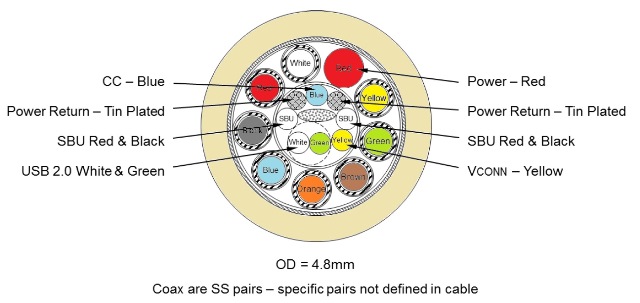
Fig. 2: Shown here is an example of USB full-featured Type-C cable cross section, using micro-coaxial wires for USB SuperSpeed. There are four groups of wires: USB D+/D− (typically unshielded twisted pairs), USB SuperSpeed signal pairs (coaxial wires, twin-axial, or shielded twisted pairs), sideband signal wires, and power and ground wires. In this example, the optional VCONN wire is shown. (Based on Figure 3-19 of the Universal Serial Bus Type-C Cable and Connector Specification, Revision 1. 2, March 25, 2016)
A number of companies are now supplying connectors to support Type-C. A few recent examples (Fig. 3 ) are the USB-C receptacle (Cat. No. 953) and plug (Cat. No. 954) from Keystone (http://electronicproducts-com-develop.go-vip.net/Interconnections/Connectors/Plugs_sockets_support_USB_3_1_Type_C.aspx), the vertical-mounting KUSBVX-SMT-CS-B30TRC and KUSBVX-SMT-CS-W30TRC from Kycon (http://electronicproducts-com-develop.go-vip.net/Packaging_and_Hardware/Enclosures_Cabinets_and_Chassis/USB_3_1_Type_C_connectors_mount_vertically.aspx), and the Series 898 SuperSpeed Universal Serial Bus 3.1, Type C from Mill-Max (http://electronicproducts-com-develop.go-vip.net/Interconnections/Connectors/USB_3_1_Type_C_receptacle_offers_2X_faster_transfer.aspx). It should be noted that with Type-C, the pins are recessed within the connector to provide extra protection.

Fig. 3: The recently introduced Type-C connectors shown above are made by (from left to right) Kycon, Keystone, and Mill-Max.
Advertisement


