RF circuits are very dependent on physical layouts and parameters. The wavelengths determine transmission line characteristics, antenna sizes and types, as well as the types and values of matching components to assure maximum power transfer from RF transceivers and antennas. This means that often, the best performance from RF designs comes when the entire section is somewhat modular, self-contained, and almost operates like an island unto itself. This also allows complete control over the digital, analog, and RF ground planes and power planes to achieve the best layout.
But there are times when a central processor unit will be far removed from the antenna or antennas. It is infeasible to make very large PC boards. PCB traces act as transmission lines and the longer the trace, the more difficult it is to control. What’s more, these RF traces need to be isolated from other circuitry like noisy digital processors and switching-power devices so as not to corrupt signals.
It is possible to use well-characterized coaxial cables to allow amplified signals to traverse box-to-box or even longer distances. This is typically done with high-power RF signals that need to drive a large antenna, such as broadcast-TV-station transmitters. But, this technique introduces its own set of issues. First, costly connectors and cables add to the bottom line. Next RF-signal loss and distortions occur, and standing-wave ratios (SWR) can require adaptive tuning circuitry since conditions do change from time to time.
This issue can be exacerbated when split RF links are used. For example, a half-duplex link can use the core processor to enable signal flow through isolating switches or multiplexers. This means that signals on both sides of the switch need to maintain signal integrity and match impedances (usually 50 Ohm) so as not to degrade the waveform in any way. Note, receiver selectivity of specific antennas is useful to geo-locate using RF as well as allowing a controlling processor to select the best-performing antenna and radiation pattern for the specific link in progress.
Light Years Ahead
An interesting approach to solve these issues comes from Avago Technologies, which has introduced a solution to use fiber optics as a transfer medium for RF signals. This solves the medium-to-long distance issues associated with coaxial cabling and SWR, while providing a PCB-friendly interface that can replicate the same transmit signals to drive single or multiple transmitters.
The AFBR-1310Z and the AFBR-1310xZ parts use single-mode 1310 nm fiber to pass analog 200 MHz to 5.5 GHz frequency range signals. The AZ parts use a SC/APC pigtail while the BZ parts use an LC/PC pigtail, which are flex SIP headers that can be inserted into a receptacle (for modular use), or soldered directly onto the PC board.
These parts combine a 5 V 50 Ohm linear RF amplifier coupled to an InGaAsAl/InP Fabry-Perot LASER that takes advantage of a floating monitor photodiode for flexible loop control (Figure 1). Note how the RF input is self-biased and AC-coupled to block any DC offsets.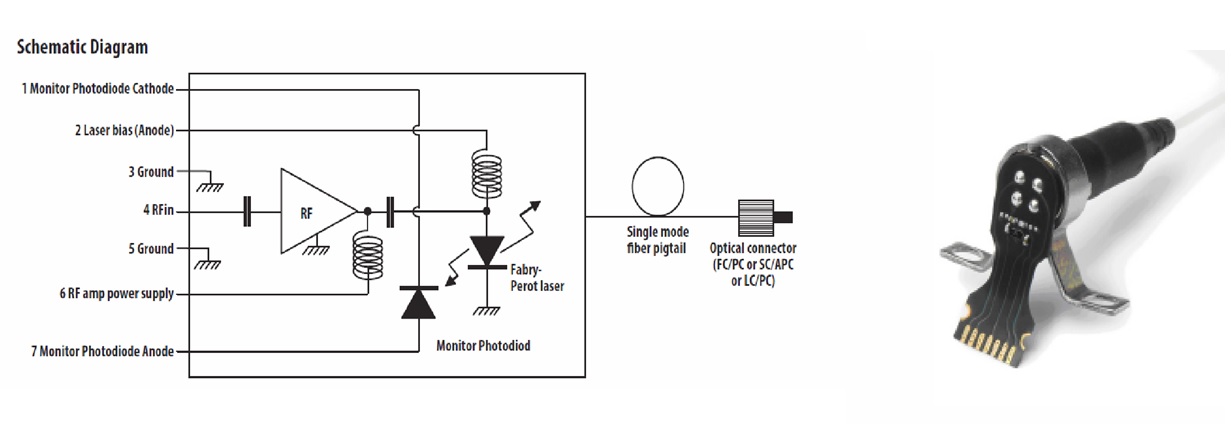 Figure 1: AC-coupled RF self-biased 50 Ohm inputs make these fiber transmitters easily couple to RF circuitry allowing wider distribution of RF signals. (Source: Avago Technologies)
The Receiving End
To complete the link, Avago offers the 3.3 V AFBR-2310Z fiber-optic receiver for multi-GHz analog links. Also rated for 200 MHz to 5.5 GHz ranges, the receiver part is optimized for the same 1310 nm wavelength, but can also be used from 850 nm to 1600 nm wavelengths.
Note the shape of the shroud allowing it to be assembled into a customer box or wall fixture (Figure 2). Like the transmitters, these receiver parts use flexible circuit board connects for socketing or direct soldering to a PC board, and they also exhibit 50 Ohm output impedances for easy coupling into distribution RF amplifiers and antennas.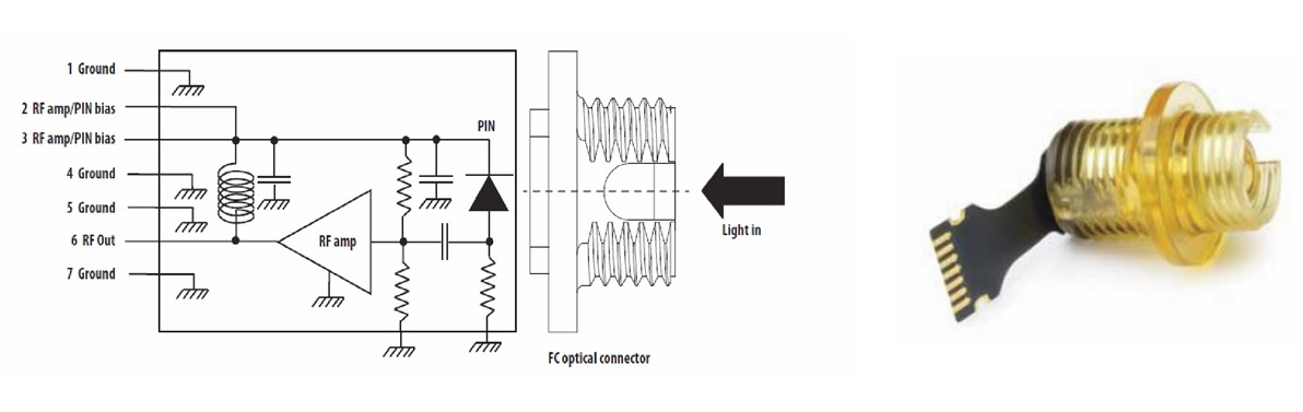 Figure 2: Completing the fiber-optic RF link, the receiver presents the clean 50 Ohm-signal back out. Note: AC coupling is required externally in this case. (Source: Avago Technologies)
Satellite distribution centers, remote radio stations, in-building communications, and even in-vehicle systems can take advantage of fiber optics to eliminate the threat of ESD, noise, EMI, and RFI as well. This is a technology to keep an eye on.
Author: Jon Gabay
Advertisement
Learn more about Avago Technologies


