Interference is becoming more common and more severe in today’s increasingly crowded wireless spectrum. Given the complex and dynamic nature of many wireless signals, equally dynamic measurement tools are needed to effectively troubleshoot and maintain deployed systems.
One such tool is real-time spectrum analyzer (RTSA) capability, which provides high-speed, gap-free measurements and a variety of informative display modes. When these functions are added to a handheld spectrum or combination analyzer, field personnel can use a single instrument to detect, locate, and resolve issues such as co-channel interference and uplink interference (Fig. 1 ). Continuing advances in digital signal processing (DSP) and analog-to-digital converters (ADCs) are putting RTSA within reach of more users.
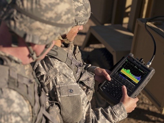
Fig. 1. With frequency coverage to 50 GHz and RTSA functionality, advanced handheld analyzers enable efficient troubleshooting of interference in the field.
Reviewing common interference issues
Any type of interference can have a profound effect on performance metrics such as quality of service and quality of experience. Fortunately, troubleshooters can focus on a few types of interference that commonly cause problems in wireless systems. Relative to signal interaction, the interference may be co-channel (CCI), adjacent channel (ACI), or intermodulation distortion (IMD). From the network-operation perspective, there may be interference in the downlink or uplink between a base station and a mobile unit.
Within a wireless system, interference is often caused by closely situated cell sites and base stations that are always transmitting. Noise affects downlink connections to mobile users, leading to increased uplink noise at the base station antenna and, ultimately, reducing cell-site capacity. The impaired signal-to-interference ratio shows up in the channel quality indicator (CQI) reports generated by mobile devices and sent to the base station. Low CQI results in greater retransmission of data and a decrease in network speed.
In commercial digital wireless networks, external interference is often the result of the slim frequency guard bands that exist between operators. Also, any illegal use of the frequency spectrum will exacerbate these problems.
Assessing traditional interference analysis
If interference exists within a network, typical performance-monitoring tools may report a variety of issues: connection failures, high signal-to-noise ratio (SNR), and a rising uplink noise floor when traffic is low.
The next step is detecting and locating the source of the problem. The traditional approach has been to use a directional antenna connected to a spectrum analyzer, and this works well when the culprit is sending a relatively constant signal.
Detecting non-constant signals requires use of the “maximum hold” display feature of most swept-tuned and FFT-based spectrum analyzers. However, because these analyzers often have large dead times during sweep reset or FFT processing time, max hold can be time consuming as it gradually accumulates the details in “bursty,” or random-like, signals. It may also miss exceedingly brief signals.
Utilizing gap-free measurements
An RTSA is an FFT analyzer operating in a mode that continuously processes incoming data, and this solves the problems of analyzer dead time and random-like signals. The analyzer is set to a start or center frequency of interest and a frequency span less than or equal to its maximum real-time analysis bandwidth. With its large buffer memory synchronized with the DSP and display engines, the analyzer can process and empty the memory fast enough to capture all incoming data (Fig. 2 ). The stream of gap-free measurements enables detection of dynamic transients and narrow pulses that are within the analyzer’s real-time bandwidth.
RTSA performance is a function of the underlying ADC and DSP hardware. In current-generation analyzers, maximum real-time bandwidth ranges from 10 MHz in handheld analyzers to 1 GHz in benchtop signal analyzers. In field troubleshooting, 10 MHz is often sufficient for most of today’s over-the-air applications.
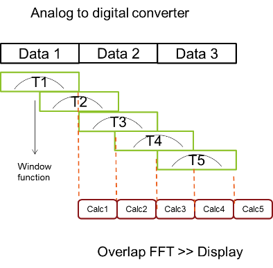
Fig. 2. Gap-free RTSA processing uses weighting, or “window,” functions and overlapping FFT calculations to enhance the measurement and display of dynamic signals.
Two more crucial and related characteristics are “100% probability of intercept” (POI) and minimum detectable signal. POI defines the shortest signal duration that the analyzer can detect with 100% probability and full amplitude accuracy; the minimum detectable signal is shorter and is a function of raw ADC and DSP performance. In handheld analyzers, typical values are 12 µs for POI and 22 ns for minimum detectable signal.
When chasing interference in the field, the other key specification is spurious-free dynamic range (SFDR). The better the analyzer’s front-end performance, the more easily RTSA can discern low-level signals of interest from internal spurious signals.
Mitigating interference problems
CCI refers to any interfering signals that are either at the same frequency as the serving carrier or are within its channel bandwidth. In digital wireless systems, the interfering signals have an effect only when synchronized with the baseband frames.
Typically, CCI has a greater effect on the downlink because the system has no direct feedback regarding this type of interference. For example, if an interferer blasts RF energy into the middle of an LTE downlink channel, the mobile unit detects poor SNR and, in response, transmits more power on the uplink.
Detecting and troubleshooting CCI can be difficult because interferers are often hidden beneath the carrier signal. When using a traditional spectrum analyzer, the only reliable way to detect such signals is to shut off the carrier transmitter — and this is too disruptive to be practical in the field.
With RTSA, the density display is a spectrum measurement that adds a third dimension — frequency of occurrence — to frequency and power. The display is color-coded to show the rate of occurrence, ranging from red (often) to blue (less often). Because interferers differ from carriers in terms of signal-level distribution, the density display makes it easier to detect multiple signals in the same channel (Fig. 3 ).
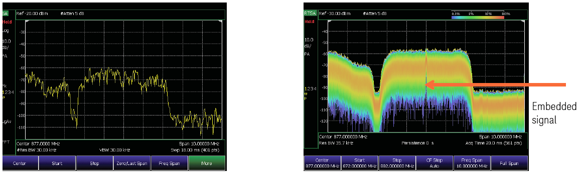
Fig. 3. Compared to a conventional spectrum analyzer (left), RTSA and the density display (right) reveal the presence of a two-way FM signal in the center of a W-CDMA signal.
In broadband systems such as LTE, noise in the uplink limits network capacity and performance. Because cell sites and mobile devices within a system operate on the same frequency, controlling all noise — internal and external — to the system is crucial.
With RTSA, the ability to perform a gap-free capture and then apply the density display enables the user to find the time signature of a specific signal and see the statistical distribution of power in the signal. This makes it easier to separate various signal types, even within the same network.
Checking for hardware problems
More than half of interference issues are caused by malfunctioning RF subsystems or components within a network, and the most common culprits are antennas and cables.
In an antenna, the key performance parameter is return loss, or voltage standing wave ratio (VSWR). If a transmit antenna has a decrease in return loss, less energy will be transmitted to the coverage area. Mobile units respond by increasing transmit power, and this causes noise to increase at the base-station receivers. Field personnel may misinterpret this as external interference, sending them on a wild goose chase. Whenever external interference is suspected, a good first step is to test (i.e., sweep) the antenna using a suitably equipped handheld analyzer.
Cabling is exposed to a wide range of environmental forces and, over time, connectors may corrode and cables can bend. These types of degradations often lead to an increase in cable loss, reducing the received power level near the cell edge and causing declining SNR. Performing routine cable-loss measurements relative to the link budget is a proactive way to avoid interference issues within the network.
Interference is a symptom of many underlying problems. Handheld analyzers equipped with RTSA can help engineers and technicians quickly detect interference issues, locate the cause and, after implementing the fix, verify system performance.
Advertisement
Learn more about Keysight Technologies, Inc.


