By Warren Miller, contributing writer
Buck-boost converters are a form of switching-mode power supply that can supply a regulated DC output from a source voltage either above or below the desired output voltage. This can be particularly helpful in battery-powered applications in which the battery voltage starts out above the desired output but falls below as the battery drains. It’s useful for every engineer to understand the fundamentals of buck-boost converters because they’ve become such an important element in electronic systems.
As their name implies, buck-boost converters combine elements of both the buck converter and the boost converter, both of which can operate with either an AC or a DC input voltage source. The buck converter produces a DC output between 0 V and just below the input voltage. A common application is in a communications chassis, wherein the input voltage might be as high as 48 V but the individual board voltages might not be higher than 12 V. A buck converter might first regulate the input voltage to something closer to 12 V, and then additional converters would generate the still-lower voltages needed by the board’s MCU, memory, or FPGAs. Often, a board will require three or four different voltages, so you can see that starting with a voltage higher than what is needed by the individual devices is advantageous.
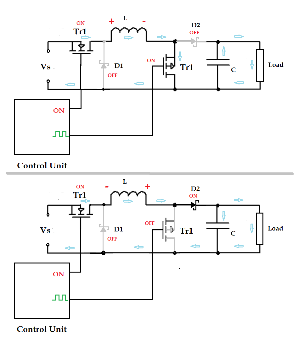
The aptly named boost converter can produce an output voltage higher than the input voltage. This is done by switching the circuit between a mode that stores energy in an inductor while a capacitor supplies the output and one that releases that stored energy in order to recharge the capacitor. When current through the inductor is shut off, the energy stored in its magnetic field gets released in a high-voltage pulse as the field collapses, and the resulting current is sent to the capacitor to boost the output voltage. The operation of a buck-boost converter in the boost mode is shown in the figures below.

Fig. 1: Buck-boost converter operating in boost mode. Image source: learnabout-electronics.org.
In the top figure, the control unit selects the switches so that the output voltage comes from the output capacitor and the current from the input source is routed through the inductor. In the bottom figure, the control unit changes the switch settings and the input voltage (Vs) is added to the voltage across the inductor (L) to charge up the capacitor to a voltage above the input voltage and provide it on the output.
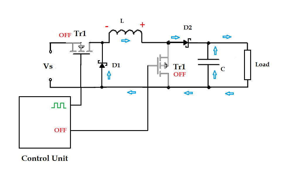
The operation of the converter in buck mode is done by turning Tr2 off at all times and then switching Tr1 on and off. Diode D1 conducts when Tr1 is off to complete the circuit and keep current flowing to the output. These two modes are illustrated in the following figure.

Fig. 2: Buck-boost converter operating in buck mode. Image source: learnabout-electronics.org.
Switching-mode power supplies are used in just about every piece of electronics, and the fundamentals of their operation can be helpful for just about any engineering discipline, not just electronics. Anyone interested in the next level of detail should check out learnabout-electronics.org. You can also check out integrated circuit manufacturer websites to look at the detailed specifications for buck and boost converters.
Advertisement
Learn more about Electronic Products Magazine


