BY STEVE LOGAN, Executive Business Manager, Maxim Integrated, www.maximintegrated.com
Sensors are everywhere today. Our smartphones and tablets are loaded with them. Our cars have temperature sensors, image sensors, and pressure sensors. Our home environments are getting more savvy.
Sensors measure all sorts of different analog phenomena:
- The proximity sensor on our phone that turns off the display
- The light sensor that adjusts the backlighting
- Air, chemical, and water flow sensors through our city pipes
- Chemical sensors at the oil refinery
- Temperature, level, and other environmental sensors at the local microbrewery
After the sensor has output the analog value, the next step is to convert the signal into a usable format. What kind of signal conditioning and analog-to-digital conversion is best? This article looks at these questions.
With all of the sensors mentioned above, analog signals can vary quite a bit. Some sensors, such as pH/chemical sensors, provide high-impedance outputs. Many others provide very low-level signals, where it can be difficult to extract the real information from the noise. And others, such as thermocouples, produce non-linear signals and are different for each type.
Low-level voltage signals
Pressure is one of the more monitored signals in the world. Pressure sensors with Wheatstone bridges are used for industrial applications. For example, pressure sensors in grocery stores weigh lunch meat, but they can also be used by dynamic scales within a warehouse conveyer belt, for which high accuracy and wide dynamic range are critical.
One example of a bridge sensor is shown in Figure 1, where an output voltage is created between +Vout and –Vout that is dependent on the excitation voltage difference and the effects to the variable resistors. Bridge sensors typically output voltages on the order of a few millivolts. A typical compression range is 1,000:1, where a 1-V total excitation voltage difference produces a 1-mV maximum between the two outputs. The excitation voltage can be increased, at the expense of taking more power.
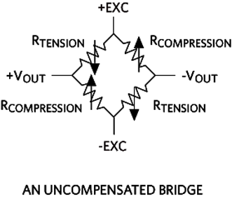
Fig. 1: Wheatstone bridges provide an output based on the excitation voltage and the compression and tension resistance.
A 1-mV maximum range does not provide a very large dynamic range to obtain the signal of interest out of the noise floor, which is typically down in the microvolts or tens of microvolts. All bridge sensors will be followed by an amplifier or a programmable gain amplifier (PGA). And that will usually be followed by an A/D converter. The majority of A/Ds offer maximum input ranges of 3 V or 5 V, so you need to amplify the 1 mV bridge sensor signal to something that uses all (or much more) of the A/D’s available voltage range.
A number of companies offer standalone amplifiers that can be configured with external resistors or digital potentiometers for amplifier gain. Many also offer PGAs that can be configured with a SPI interface. A sigma-delta A/D converter with an integrated PGA can often be the best choice today. The number of these devices has grown considerably in the last 10 years. Many of these have 16-, 20-, or 24-bit A/D conversation, and an integrated A/D plus PGA allows for the lowest possible noise.
Let’s look at the warehouse conveyer belt scale. The faster these warehouses can move their freight, the higher their throughput and profit margins. Being able to dynamically measure the package weight at the same time it’s moving from one station to the next is becoming increasingly common. With these warehouses shipping goods in a wide range of weights, a wide dynamic range and low noise are needed, along with a relatively fast sample rate.
One example IC for this circuit would be the MAX11270, which offers a good combination of sample rate, wide dynamic range, and low noise. Its maximum sample rate is 64 ks/s and the PGA’s noise level is 6.5 nV/√Hz. The device can achieve an effective number of bits of 21.0 at a 1-ks/s sample rate – or better than 1 part in 2 million.
High-impedance chemical sensors
In an application such as process control, chemical sensors are vital for keeping the mix of ingredients at the right level. Microbreweries are easy for most people to imagine. In the brewing process, the mix of ingredients is a vital in ensuring a repeatable (and pleasing) taste for consumers.
Sensors that measure pH levels are commonly used for this process control. These have high-impedance electrode signal outputs. An amplifier with a very small input bias current is required to convert this impedance signal into something more easily measured. For a chemical sensor, input bias currents on the order of pico-amps or even femto-amps are desired to reduce the total error. Here, it’s necessary to dig in to the datasheet and confirm specifications over the temperature range that the application will require.
Numerous low input-bias current opamps are available. One of those is the MAX44242. Though its input bias current is not as low as that of some other JFET amplifiers, it is lower by a few orders of magnitude than standard amplifiers and would be a good choice for this sensor interface. Figure 2 details the device's input bias current specifications over temperature.
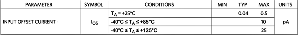
Figure 2. MAX44242 input bias current over temperature is 50-pA maximum.
Tutorial 717 from Maxim offers an in-depth explanation of key amplifier specifications for various voltage amplifier types, and temperature effects on all of these specs: https://www.maximintegrated.com/en/app-notes/index.mvp/id/717.
Communications and data center designs
Next, let’s think of a complex processor board designed into an application such as a base station or a data center. These boards have continued to draw higher power with each generation, while also trying to squeeze into a smaller space. The higher data rates yield higher power dissipation and higher temperature. Measuring temperature has gotten more important with each generation. Some of the ASICs or FPGAs will have internal temperature sensors. Some will include thermal diodes that output an analog signal. In other cases, board designers will add their own sensors around the high-power ICs.
If a system designer needs an external temperature sensor, there are a number of options, including fully buffered ICs with analog outputs, digital outputs, or temperature switches that make interfacing easy. The choice of package offers another degree of flexibility. While the majority of temperature sensors are in surface mount packages, such as SOIC or SOT23, there are also options for getting the temperature sensor off the board to get a more accurate reading of the air temperature.
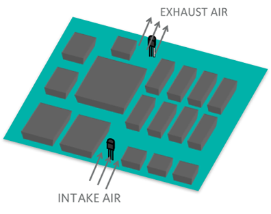
Fig. 3: Board design uses temperature sensors with leads to measure the temperature difference between the intake air and the exhaust air.
Figures 3 and 4 include an example of a leaded off-board temperature sensor. The example device, the DS18B20 sensor, uses a 3-lead TO-92 package. Having a surface mount temperature sensor package next to a large processor, ASIC, or FPGA may cause the temperature result to vary widely from another point on the board. There are arguments both ways for knowing the board temperature right next to a high-power IC, but the leaded package will give a better airflow temperature reading. It’s possible the heat in the PCB board layers may distort temperature readings for SMT devices. Many complex base station and data center board designers place one sensor at the air input and another one at the air flow output.
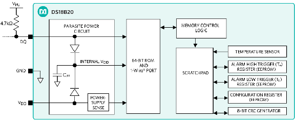
Fig: 4: The DS18B20 temperature sensor has only 3 pins with a 1-wire serial output.
Advertisement
Learn more about Maxim Integrated


