Industrial motion control covers a breadth of applications, ranging from inverter-based fan or pump control, to factory automation with more complex ac drive control, to advanced automation applications such as robotics with sophisticated servo control. These systems require sensing of a number of variables such as motor-winding current or voltage, dc link current or voltage, rotor position, and speed. The selection of variables and the required measurement precision depend on the end application demands, the system architecture, target system cost, or system complexity. There are other considerations, such as value-add features like condition monitoring. With motors reportedly consuming 40% of worldwide electric power, international regulations have increased the focus on system efficiency across the entire range of industrial motion applications (see Fig. 1 ).
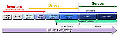
Fig. 1: Industrial drive application spectrum.
Current- and voltage-sensing techniques in various motor control signal chain topologies vary according to motor power rating, system performance requirements, and end application. In this context, motor control signal chain implementations differ by sensor choice, galvanic isolation requirements, A/D converter choice, system integration, and system power/ground partitioning. While isolation requirements usually have a significant influence on the resulting circuit topology and architecture, this article will focus on improving current-sensing measurements (as one contributing element) to realize a more efficient motor control system.
I and V measurement
A generic motor control signal chain is shown in Fig. 2 . Signal conditioning to realize a high-fidelity measurement is not trivial. Phase current sensing is particularly challenging, as this node is connected to the same circuit node as the gate driver output within the heart of the inverter block and therefore experiences the same demands in terms of isolation voltages and handling switching transients.
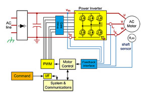
Fig. 2: Generic motor control signal chain.
The most commonly used current sensors in motor control are shunt resistors, Hall effect sensors (HEs), and current transformers (CTs). While shunt resistors don’t provide isolation and incur losses, they are the most linear of all the sensors, the lowest cost, and suitable for both ac and dc measurements. The signal-level reductions to keep shunt resistor power losses down typically limit the losses to 50 A or less. CTs and HEs provide inherent isolation, allowing them to serve high-current systems, but they are higher cost and result in a less accurate solution than what can be achieved with a shunt resistor, either due to poorer initial accuracy or worse accuracy over temperature. Quite apart from the sensor type, there are several motor current measurement nodes to choose from, as shown in Fig. 3 , with direct in phase-winding measurement being the ideal and used in the highest-performance systems.
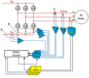
Fig. 3: Isolated and non-isolated motor current feedback
There are many topologies to sense motor current with many factors to consider such as cost, power, and performance levels, but a key objective for most system designers is to improve efficiency within their cost targets.
From HEs to shunt resistors
Shunt resistors coupled with isolated ∑∆ (sigma-delta) modulators provide the highest-quality current feedback (where the current level is low enough). There is a significant trend for system designers to migrate from HEs to shunt resistors, with an additional trend to move to the isolated modulator versus an isolated amplifier approach. Quite often, system designers replacing HEs with shunt resistors opt for an isolated amplifier and continue using the A/D converter previously used in the HE-based design. In that case, the performance will be limited by the isolated amplifier regardless of the A/D performance.
Replacing the isolated amplifier and A/D with an isolated ∑∆ modulator will eliminate the performance bottleneck and greatly improve the design — typically taking it from a 9 to 10-bit quality feedback to a 12-bit level. Analog overcurrent protection circuitry can also potentially be eliminated, as the digital filter required to process the ∑∆ modulator output can also be configured to implement a fast OCP loop.
Available ∑∆ modulators may have a differential input range of ±250 mV, with ±320 mV full scale used for OCP, which is well suited to resistive shunt measurements. The analog input is continuously sampled by the analog modulator and the input information is contained in the digital output stream with a data rate up to 20 MHz. The original information can be reconstructed with an appropriate digital filter. As conversion performance can be traded off versus bandwidth, or filter group delay, a coarser, faster filter can provide fast response OCP on the order of 2 µs, ideally suited to IGBT protection.
Reduce shunt resistor sizes
From a signal measurement standpoint, there are some key challenges associated with the shunt resistor selection, as here is a trade-off between sensitivity and power dissipation. Nonlinearity due to self-heating effects can also be a challenge using higher-value resistors. Designers are faced with making trade-offs, and further exacerbating this is a common need to select a shunt size that will service many models and motors at different current levels. Maintaining dynamic range is a challenge in the face of peak currents that can be several times the rated current of the motor and the need to reliably capture both.
In the face of these challenges, system designers are looking for superior ∑∆ modulators with wider dynamic range, or improved signal-to-noise and distortion ratio (SINAD). Isolated ∑∆ modulator offerings to date have provided 16-bit resolution with up to 12-bit effective number of bits (ENOB) guaranteed performance.
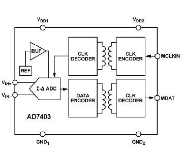
Fig. 4: The AD7403 a high-performance, second-order ∑∆ modulator
High-performance isolated ∑∆ modulator
A higher-performance isolated sigma-delta modulator would support several needs in industrial motor control designs and improve power efficiency of motor drives through shunt resistor size reduction. One industry example is the AD7403 modulator from Analog Devices (see Fig. 4 ). It is the next-generation product to the AD7401A, providing much wider dynamic range at the same external clock rate of 20 MHz. It allows more flexible shunt size selection and allows for shunt resistor usage in place of HEs at higher current levels. The chip's ENOB is 14.2 bits typ. Dynamic response can also be improved through reduced measurement latency. The device also features an isolation scheme with a higher continuous working voltage (VIORM ) than the previous generation, which can contribute to higher system efficiency via higher dc bus voltages and lower currents.
System solutions with the ADSP-CM40x mixed-signal control processor
As already noted, the implementation of a sigma-delta modulator requires a digital filter. This is traditionally implemented with an FPGA or ASIC. The advent of the ADSP-CM408F mixed-signal control processor from Analog Devices will change that design problem as it includes hardware Sinc filters, to which the modulators can directly connect. This is likely to lead to an increased rate of adoption of the resistive shunt and sigma-delta modulator technique.
Advertisement
Learn more about Analog Devices


