By Patrick Mannion, contributing editor
Designing for compliance and the smarter application of test data were strong themes at the annual DesignCon chip-and-board fest in Santa Clara. Woven in among the usual chip-and-board design and test discussions, the themes came into stark relief in the context of autonomous vehicles and the ubiquitous IoT.
“How we design automotive systems is about to change radically,” said Todd Hubing, professor emeritus of electrical and computer engineering at Clemson University, during his keynote, “How Do We Make Autonomous Vehicles Safe Enough?” While he said that the upside to having more electronics in vehicles is that “we’ll know it was the electronics that failed and not the driver,” the problem is that, given the number of driving hours, “the reliability required is more than most aerospace designs.”
Using publicly available data, Hubing, who is a consultant to various automobile and automotive system manufacturers, put the annual number of driver-related deaths at approximately 1.25 million. While complying with ISO 26262 ensures that a design meets that standard’s requirement of 10-10 fatalities per operational hour, design confidence quickly diminishes in light of the more than 50 billion vehicle operational hours in the U.S. alone.
Using a popular vehicle as an example, if that vehicle were tested to NASA satellite standards of 10 million hours between mission-critical failures, over 300 people would be killed in that vehicle in the U.S. every year.
With vehicles needing to be tested to a level higher than military and aerospace designs, Tubing described why current models for test and compliance won’t work going forward. His call-to-action starts with a wake-up call as to the number of vehicle systems that are now capable of actuating the throttle without driver input (Fig. 1 ).
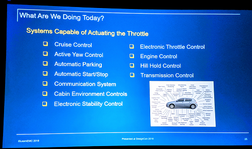
Fig. 1: The number of systems capable of actuating a vehicle’s throttle is a wake-up call to the need for a rethink of how to test and validate electronic systems.
The myriad systems include the obvious, such as cruise control, automatic parking, and transmission control, and the less obvious, such as active yaw control, cabin environmental controls, and communication systems. Hubing provided similar charts for systems that can control steering and braking without human intervention.
At issue are the many points of failure within these systems. These include unintended electrical connections such as water from condensation, rain or car washes, tin whiskers, mechanical malformation or breakage, arcing, solder balls, and component failures.
Then there are software errors, said Hubing. “A commercial aircraft has about 10 million lines of code, while a typical luxury car has about 100 million lines of code.” With this code come errors such as programming errors, incompatibilities between systems, unforeseen situations (inputs), and incompatible hardware changes.
Finally, there are EMC problems, which can derive from electric field disturbances, power disturbances, crosstalk, electronic discharge, and radiated electromagnetic fields.
From all of these potential sources of failure, Hubing described the three weakest links as safety-critical reliance on:
- Analog sensor inputs whose accuracy cannot be validated
- Undefined software whose performance cannot be modeled or validated
- Individual hardware components (particularly microcontrollers)
While Hubing pointed to the usefulness of the well-known V-model (see “Automotive security demands an infinite software development lifecycle”) when applied in the correct requirements and validation sequence, “The problem is that it’s not working that way: Everything is happening in parallel.” Designers are building prototypes, then testing, then modifying and testing again. “So you end up designing components to pass the test” instead of designing components to meet the requirements.
Hubing’s “horror stories” of instances in which modifications were made on the fly to get a system to pass the test emphasized the danger of such a process. These manipulations of hardware or software may get the system to pass the test, but then no one fully understands the implications of that manipulation. Not only does this undermine the integrity of that specific design, but because it “worked,” that manipulation gets carried through to the next generation of vehicles without solving the underlying problem.
To address the fundamental problems, Hubing described three things that need to be done differently:
- Design for compliance.
- Recognize and record all component and system failures and store them permanently, including details on what happened in the minutes leading up to an accident.
- Don’t allow safety to be compromised by any single detected component failure or any number of undetectable component failures.
While the difficulty of predicting component failures is clear, Hubing underscored the importance of designing for compliance instead of designing “to pass a test.” To this end, Hubing suggests that the industry impose a single test wherein designers get “one shot” at passing. In this way, he said, the designers will make sure that it is correct before it goes to test “so it cannot possibly fail,” given the consequences of having to start from scratch versus improvising at the last minute.
Accelerating EMI/EMC compliance testing
While Hubing may be right with regard to designing for compliance, few tools can accurately model the EMI/EMC performance of a system for the “real world” to the extent that compliance testing becomes a formality instead of a hurdle. With the emergence of the IoT, EMI/EMC compliance is increasingly problematic as more devices incorporate wireless communications and become both interferers and subject to interference simultaneously.
To test a system, it typically must be sent to a test house with an anechoic chamber, which can cost as much as $2,000 per day and take four or five days, said Chris Loberg, senior technical marketing manager at Tektronix. “Then if it fails, they have to do it all over again,” he said.
IoT and wireless connectivity requirements are exacerbating the problem of EMI/EMC compliance, but it’s a constant issue. Simple DC/DC converters, part of any power supply, are switching at 1 to 3 MHz and producing baseband noise in the gigahertz, said Ken Wyatt, an independent EMC consultant at Wyatt Technical Services, LLC. Quoting numbers from Intertek, Loberg said that up to 50% of products fail EMC compliance on the first go-around. Still, pre-compliance testing is time-consuming, requires expensive equipment, and suffers from a lack of reporting tools, “so many companies skip it,” said Wyatt.
To address the cost and time factor, Tektronix uses DesignCon to introduce the EMCVu, an all-in-one EMI/EMC pre-compliance testing and troubleshooting solution. At the heart of EMCVu is the Tektronix USB-powered RSA306B spectrum analyzer and SignalVu-PC software, with the EMCVu option, to control the test hardware and do the reporting (Fig. 2 ). Around these are various accessories, such as an amplifier, near-field probe, radiated test antennas, tripod, and cabling. The losses and gains of each of the relevant accessories have already been captured in the software and accounted for during the measurements.
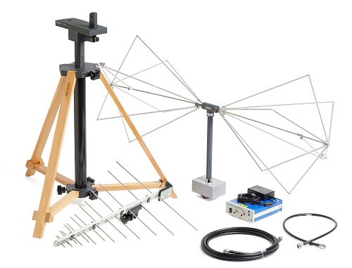
Fig. 2: The Tektronix EMCVu is a cost-effective EMI/EMC pre-compliance testing solution that lets designers test and debug before going to formal compliance testing.
The full kit costs $26,655 (MSRP), which Loberg said is the same as a single trip to an EMC test house, but it greatly reduces the odds of having to make a second or third trip. However, some accessories may already be in-hand, so the basic kit starts at under $6,400.
New AI approaches make test data more valuable
One of the lost opportunities when it comes to test and measurement is making better use of data, but that’s changing. Instead of gathering and putting it into cold storage for reference at a later time, test companies are now finding ways to turn data into more of a real-time tool using local or cloud-based analytics.
This analytics capability is one of the highlights of PathWave, a new design and test software platform that Keysight Technologies introduced at DesignCon (Fig. 3 ). PathWave represents the latest thinking in the industry on how test should be done in that it connects every step of the design and development path from design and simulation to prototype and test and all the way through manufacturing, said Brigham Asay, director of strategic marketing at Keysight.
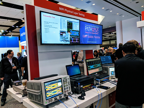
Fig. 3: Keysight introduced PathWave, an open, scalable, and predictive “big data” test workflow and data analysis platform.
Key attributes are that it’s open, scalable, and predictive. The latter comes from its use of analytics tools that identifies trends, monitors the use and health of each test resource, and captures and analyzes “big data” for more effective workflow processes. This analysis can scale from local to cloud-based, depending on the workflow and test requirements.
The workflow process was emphasized by Asay, who pointed to users’ abilities to reconfigure the interface using open application programming interfaces (APIs) for rapid customization.
Tektronix also showed off a predictive scheme, using its DPO70000 real-time oscilloscope. Its version uses machine learning to program “neurons” so that it can replace traditional S-parameters and IBIS-AMI models to improve speed and accuracy.
Advertisement
Learn more about Electronic Products MagazineTektronix


