By Bonnie Baker, Maxim Integrated
Encoders are integral parts of motor-control systems that sense mechanical motion, then generate digital signals in response to that motion. The trend today is to create smaller mechanical and electronic devices, and the motor as well as its encoder are part of this trend in applications such as robotics, drones, medical equipment, and handheld devices. The major challenge that designers now face is trying to fit the necessary number of devices into the encoder’s shrinking space allocation.
Whether the system is an automated pick-and-place (x-y positioning), an automobile (assisted lane detection), or a robotic arm, the position feedback information that an encoder provides is an integral part of the motor-control system (Fig. 1 ). Encoders can provide either incremental or absolute positions in motion applications. When an application needs a relative motor position, an incremental encoder is useful. One uses these types of encoders with AC induction motors. In contrast, pairing the absolute encoder with permanent-magnet brushless motors assists in servo applications. The encoder feedback ensures synchronization of the motor stator by providing rotor direction, speed, and position.

Fig. 1: Human vs. robotic arm, where encoders abound.
Embedded in an encoder is a motor position-sensing device and several analog-to-digital converters (ADCs). These circuits translate the motor’s motions such as speed, direction, and shaft angle into electrical signals that they provide to the system microcontroller or processor. In the example of Fig. 2 , the encoder uses an optical wheel that connects to a motor stator. The encoder’s output signals provide information that allows the system’s microcontroller to determine the speed of the stator and thereby control the speed of the rotation of the motor and optical wheel.
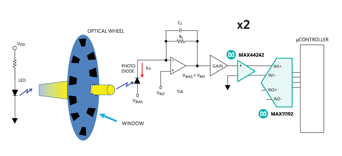
Fig. 2: Basic sensing circuit for an optical encoder.
The optical encoder uses an LED and a photodiode positioned opposite one another with the windowed optical wheel between them. The illumination from the LED is constant as the optical wheel turns. The LED light shines through each wheel window one at a time. As the LED light shines through a window, the photodiode at the input of the transimpedance amplifier (TIA) converts the impinging light into a current (IPD). The IPD current flows through the feedback resistor, RF , to create a voltage greater than VREF at the output of the TIA.
The signal travels through a gain block and then the ADC-driving amplifier — in this case, the MAX44242 — which is a 180-MHz, low-noise, fully differential successive-approximation-register (SAR) ADC driver. Next to it is the ADC, which continually samples the driver output to construct a square wave over time.
The diagram in Fig. 2 illustrates only one channel of an optical encoder, but encoders typically have at least two identical signal channels, each focusing on different windows. The appropriate ADC encoder topology thus utilizes a dual, simultaneous SAR ADC — in this example, the MAX11192. Dual encoders are available with a 12-, 14-, or 16-bit resolution, with higher-resolution ADCs providing extra sensitivity and positioning accuracy. For this encoder, the dual, simultaneous sampling SAR ADC takes consistent snapshots, providing an instantaneous picture of the encoder’s motor direction, speed, and position. Fig. 3 shows an example of the output of a two-channel encoder.
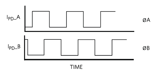
Fig. 3: The optic output of an encoder.
Encoders produce pulses, which indicate movement over short distances that the system must then interpret, such as by counting pulses to convert them into position information. There are two counting methods applied to the encoder’s output:
- A count of pulses indicates movement and speed over time.
- The channel order of the ØA compared to ØB indicates the direction.
The shrinking encoder
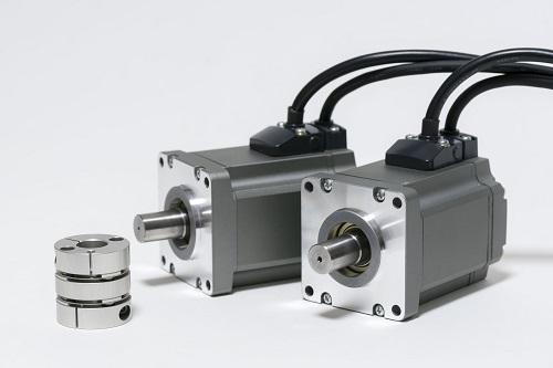
Fig. 4: The encoder continues to shrink in size.
Ideally, encoders will have all of their electronics inside the housing or donut because having the PCB inside the encoder minimizes interconnections. But as the encoder’s cubic area lessens to match shrinking motors, the PCB’s square area also reduces in size. Furthermore, with the space inside optical encoders continuing to tighten, it has become even more critical to verify device layout in the development phase. Small motor encoders can have a diameter as small as 25 mm with a shaft diameter of 4 mm, so the design challenge becomes the process of populating the smaller PCB with smaller devices.
The components depicted in Fig. 2 , plus various capacitors, must all fit on the PCB of an encoder (Fig. 4 ). In this case, the MAX11192 family helps meet tight space restrictions by offering a TFDN plastic package option, which has 3 x 2-mm dimensions and a 0.75-mm clearance. Such ultra-small package options are allowing the shrinking donut shape and internal PCB size of motor encoders to continue housing all of the needed electronics.
Bonnie Baker is a seasoned analog, mixed-signal, and signal-chain professional. She is a published author and the author of “A Baker’s Dozen: Real Analog Solutions for Digital Designers.” Bonnie has a Masters of Electrical Engineering from University of Arizona (Tucson, Arizona) and a bachelor’s degree in music education from Northern Arizona University (Flagstaff, Arizona).
Advertisement
Learn more about Maxim Integrated