In my role as a senior applications/systems engineer supporting analog and digital temperature sensors, I get a lot of questions about temperature sensor applications. Many of them are about the analog-to-digital converter (ADC). ADCs are super-important and I spend a lot of my time talking about them, including what the ADC means to system accuracy and how to understand and achieve maximum system accuracy with a chosen sensor.
Temperature sensors are used in high-power–switching power-supply designs that require monitoring of power transistors and heat sinks. A battery-charging system needs a temperature sensor to monitor the battery’s temperature so that it can safely charge and optimize battery life. Home thermostats need a temperature sensor to monitor the room temperature to control the heating, ventilation, and air-conditioning system accordingly.
In these applications, a common method of temperature measurement uses a negative temperature coefficient (NTC) thermistor. These thermistors are resistive devices that change resistance with temperature.
A newer, more efficient, and accurate approach to meeting today’s temperature-sensing needs is a silicon-based thermistor, which is a positive temperature coefficient (PTC) device. A PTC is not a resistive device but rather a current-mode device. Silicon operating in current mode provides a linear output voltage based on temperature.
Whether you use an NTC or PTC, your design will need an ADC and a microcontroller (MCU) to measure the voltage output from the thermistor. In this article, I’ll review the many advantages of silicon-based thermistors with an MCU and discuss the pros and cons of both NTC and PTC thermistors.
MCU selection
You have many options when selecting an MCU, but the odds are that this component has already been selected by the time you’re choosing the temperature sensor. What you can focus on are the ADC peripheral specifics that you should know for temperature sensing.
ADC selection
There are many different types of ADCs. The two most popular are successive-approximation-register (SAR) ADCs and delta-sigma ADCs. Delta-sigma ADCs offer high resolution (up to 32 bits of resolution) but have a slower sampling speed. SAR ADCs are the oldest and most common type of ADC, with 8 to 18 bits of resolution and a faster conversion speed. For temperature sensing, either ADC type is a good choice.
ADC resolution
The number of bits for the ADC will determine the resolution, not the accuracy. Resolution is the step size that the ADC will use to measure the analog voltage applied to the ADC pin. The number of bits of resolution along with the voltage reference (VREF) will set the value of the ADC step.
For example, a 10-bit ADC has 210 = 1,024 discrete least significant bits (LSB), and a VREF of 3.3 VDC will give a resolution of 3.3/1,024 = 0.003226 VDC per ADC LSB. A 16-bit ADC will have 216 = 65,536 LSBs of total resolution, with a voltage resolution of 0.000005035 VDC per ADC bit. More ADC bits means higher resolution for the measurement, which can lead to a more accurate temperature.
Don’t confuse accuracy with resolution. The resolution is the ability to see the changes in the measured circuit’s value. A typical MCU ADC for temperature measuring runs from 12 to 16 bits of resolution. You will find that an 8- or 10-bit ADC will not provide enough resolution to see the accuracy of the thermistor and will have a larger temperature step size that is usually not acceptable.
Oversampling for higher resolution
Oversampling is a method of averaging measurements to improve the resolution and signal-to-noise ratio. Oversampling works by summing multiple temperature measurements with noise, then averaging to get a more accurate value. For each additional bit of resolution, the signal must be oversampled by a factor of 4. For every eight oversamples, the resolution will increase by 2 bits: 16 oversamples will increase a 10-bit ADC to 14 bits of total resolution.
You can use any number of samples (N#) in your application to get the resolution that you need for your design if the number of samples are above the Nyquist rate. The Nyquist rate is how often you want an actual temperature reading. The total number of samples has to be at least N# times faster than the actual desired temperature result.
Adding some dithering noise to the input signal when using the oversampling method can improve the resolution error. In many practical applications, a small increase in noise is well worth a substantial increase in measurement resolution. In practice, placing the dithering noise outside the frequency range of interest to the measurement can subsequently filter out this noise in the digital domain, resulting in a final measurement in the frequency range of interest with both higher resolution and lower noise.
The best method of providing the dithering noise is to separate the common-collector voltage (VCC) of the thermistor divider and the VREF (using the internal VREF of the MCU for the ADC). Do not place a capacitor on the resistor-divider voltage sense line. The circuit noise will, in many cases, be sufficient to dither the resistor-divider voltage for averaging. The dithering noise must be equal to four or more bits of amplitude. A 10-bit ADC with a VREF of 3.3 VDC will have a voltage step size of 0.0032 VDC. The dither noise must be, at minimum, four bits of resolution above and below the expected temperature measurement. The minimum dither noise for a 10-bit ADC needs to be ±0.0128 VDC (0.0256 VDC peak to peak) above the least significant bit of the ADC or greater in order to provide the necessary levels to properly increase the ADC bit resolution by averaging.
After the ADC reads in a bit value and you calculate the temperature, you can store that value in a first-in-first-out (FIFO) software array. As a new value comes into the array, the oldest sample is dropped and all of the other samples shift to the next corresponding cell, thus creating a FIFO. It is possible to apply this averaging method to any of the values used in a temperature-conversion process, including the temperature, the ADC bit value, the divider voltage, or even the calculated resistance. All of these factors will work very well when averaged.
Fixed point or floating point
MCUs may have floating-point-unit hardware inside or a firmware library available if you must do the floating-point math without the hardware. Quick examples of 32-bit non-floating-point devices include Arm Cortex-M4 devices; the versions with floating point are labeled Cortex-M4F. Having floating-point hardware inside the MCU speeds up calculation times and requires less power than using a fixed-point device and a floating-point firmware library.
Having a fixed point means that only whole numbers above zero can be used. For example, 1 + 1 = 2, the average is 1. If you add 2 + 1 and get 3, the average is 1.5. In fixed-point calculations, the result will be 1 with no numbers below the decimal point.
When measuring a temperature with fixed point, you will only be able to see and reference temperatures in whole numbers: 22°C, 23°C, 24°C. Floating point can show a temperature with greater resolution: 22.1°C, 22.15°C. The math with which you calculate the temperature is easier with floating point, or you can use a lookup table with interpolation. You can also use a lookup table with fixed point and single-digit resolution, and that is acceptable for many applications.
Selecting a thermistor
There are two types of thermistors: NTC and PTC, often thought to be the same type of device. This is not correct. The NTC is a resistive device that changes resistance with temperature. The implementation of an NTC entails placing a resistor on top of the thermistor and applying a regulated voltage, as illustrated in Fig. 1. When the temperature changes, the resistance changes in the thermistor, changing the voltage drop across the RBias resistor. The output at the center of the divider resistor is an analog voltage and will be measured by an ADC.
A PTC is a silicon device that operates based on a current. As the temperature changes, so does the conducted current. Most PTCs operate using a constant-current source, as shown in Fig. 2. When the current changes, the voltage supplied by the current source changes.
An ADC measures the change in voltage and the measured value is then converted into a temperature.
You can also use PTCs just like an NTC thermistor with an RBias resistor, as in Fig. 1. The top resistor will act like your current source. PTCs typically have better thermal sensitivity to temperature changes and can be more responsive to small changes versus an NTC under the same conditions.

Fig. 1: Voltage-divider circuit implementation (left) and Fig. 2: Constant-current circuit implementation (right)
Another benefit of a PTC is that it has a linear output at the Vtemp connection (as shown in Fig. 3), making it easier to calibrate. A linear output at the Vtemp connection also makes the device more accurate across the entire temperature range.
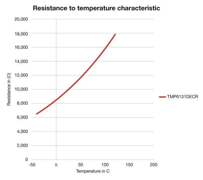
Fig. 3: PTC thermistor linear resistance slope
The NTC has a nonlinear output similar to that shown in Fig. 4 and may require a three-point calibration in a temperature chamber to allow for slope compensation, along with an offset error adjustment to be accurate across the full temperature range. The nonlinear slope of the NTC is not consistent at providing stable temperature information across the entire temperature range without calibration.
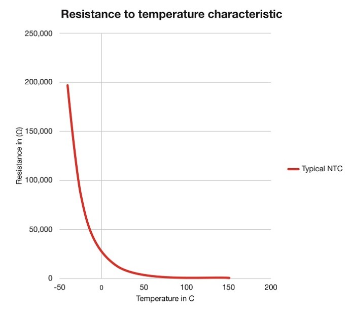
Fig. 4: NTC thermistor nonlinear resistance slope
Under normal conditions, an NTC can use a 12-bit ADC with a reasonable temperature resolution, especially at colder temperatures. A PTC, however, will usually require a 14-bit ADC to be able to get enough resolution to see the temperature steps. A PTC will need a 14-bit ADC across all temperatures, but an NTC will need a 14-bit ADC to measure temperatures above 60°C.
Adding an RBias resistor to the top of a PTC will reduce its dynamic range. The lower dynamic range is the reduced voltage feedback for the ADC; that’s why a PTC needs 14-bit ADC resolution. The lower dynamic range will cause a larger temperature error measurement, however, because of the linear slope of the PTC. A single-point offset at room temperature will calibrate the PTC across the entire temperature range. For a PTC-based system, this will make the temperature measurement more accurate than a typical (and equally specified) NTC-based system across the entire temperature range.
Ratiometric

Fig. 5: The ratiometric approach, powering the resistor divider and VREF from the same supply
The term “ratiometric” describes the captured ADC value, which can change in proportion to a change in the supply voltage. When the VCC power supplied to the voltage divider of the temperature-sensing circuit also supplies the voltage used for VREF, as shown in Fig. 5, it is then ratiometric. Any change in the VCC would then change similarly and simultaneously at the divider and VREF, affecting the measured value of the ADC and therefore minimizing the potential differential error between these sources.
The ratiometric approach can increase total accuracies in a system. It’s important when implementing a thermistor-based temperature sensor that is not using averaging or oversampling to use the same voltage supply for both the voltage divider and the VREF of the ADC.
Filtering
Using a capacitor at the voltage divider is not required in most cases and should not be used when employing the ratiometric approach with a single-ended ADC. For a differential VREF/ADC input, you would generally place a capacitor across the ADC inputs and the VREF inputs.
Filtering the Vtemp when using the ratiometric approach will change the voltage response at the sense line but not for the ADC VREF. Therefore, adding a filter would increase the differential error between the VREF and VCC input to the resistor divider.
When not using the ratiometric approach, adding capacitance at the voltage divider can filter the voltage, smoothing out noise and voltage changes that would otherwise create an error in the measurement. Adding a capacitor to filter the VREF is also a good idea. Sometimes the VREF is internal and does not need extra filtering. Adding a capacitor to the Vtemp line can increase the response time to temperature changes. If the measured temperature is slow to respond and does not require immediate action, then this filter can have benefits.
An alternative approach would be to add a capacitor to VCC right at the top of the resistor divider to filter noise in the system for the temperature measurement. If using the ratiometric approach, adding the same capacitor to the VREF will keep the voltage variations consistent for both supplies.
Buffers and amplifiers
Amplifiers can increase the dynamic range on thermistors. All operational amplifiers have potential offset error and gain errors. Selecting an operational amplifier that will have minimal impact on the accuracy and offset will take some effort. The calibration required to correct the offset and gain errors may be more costly than stepping up to a higher-quality ADC. Some MCUs have internal operational amplifiers. Many DS ADCs have integrated PGAs for this very purpose (buffering/gain). Some SAR ADCs have these features as well.
Unity gain buffers are sometimes used to prevent droop or loading to the resistor-divider circuit. When the ADC samples the thermistor-divider circuit, the inrush capacitance from the ADC can cause several millivolts of droop to the measurement. If you have enough resolution in the ADC, you will see this as an error in the temperature measurement. If you add a capacitor directly to the ADC pin equal to 10× the ADC capacitance, you can compensate for the inrush current of the ADC capacitance without resorting to buffers. The typical ADC capacitance is 3 pF to 20 pF. Adding a capacitor of 30 pF to 200 pF as close to the ADC pin as possible will have minimal impact on the measurement or thermal response of the thermistor.
Drift
Because a PTC thermistor uses silicon as its base material and has a linear slope, as a result, the current through the PTC has very low drift over time and temperature. An NTC typically has a temperature dependency on the resistance of the material used that will change over time at high temperatures. An NTC has a beta value to define the temperature coefficient of resistance in parts per million (ppm) across temperature and will also have a ppm drift over time.
Deriving a temperature from the ADC
The NTC thermistor temperature is based on the resistance of the device. Many designers use a lookup table to find the resistance at a specific temperature and then calculate (by linear interpolation) the actual temperature between each 1°C temperature step. To minimize the size of the lookup table, you can use a 5°C lookup table, but the interpolation error will be a little bit higher. For most designers, 0.5°C is more than enough resolution, so a 5°C table with interpolation ends up being good enough.
PTCs are based on the actual current through the device and are usually defined by a formula. PTCs are based on a third- or fourth-order polynomial. The fourth-order polynomial has a more accurate curve fit (R2), with 1.0000% to 0.9999% accuracy, to provide temperature information. The Steinhart-Hart equation uses a third-order polynomial with natural logs to calculate the temperature.
More designers recognize the Steinhart-Hart equation because it was originally created for the NTC many years ago. Although you can use the equation for NTCs or PTCs, today most high-accuracy PTCs rely on the fourth-order polynomial.
Calibration
All NTCs and PTCs require calibration in order to be accurate. Some NTCs are available at tighter tolerances and beta values, which can seem to eliminate calibration; however, the thermistor is not the only component in the system. The VBias resistor has a tolerance and a ppm over temperature; the VCC has an error in the voltage as well as a voltage shift over temperature. The total system accuracy may be further out of tolerance than expected, and the accuracy may not be what you desire.
An NTC typically requires a three-point calibration to adjust for slope error and an offset to correct for the total error. A three-point calibration requires both a temperature chamber and time in order to collect the errors across temperature. A PTC will have a larger offset error to begin with, given process deviations in silicon, but it is correctable across temperature with a single offset adjustment. In most cases, you can make the offset adjustment at room temperature during the final programming of the assembly; you don’t need a temperature chamber nor time for someone to do the calibration.
Conclusion
NTCs and PTCs are both simple to implement, with low component counts and a low cost. However, an NTC may require a more costly calibration method with increased drift over time.
A PTC offers a better way to conduct temperature measurements. A simple offset correction is the only calibration required across temperature. A PTC is very accurate, and the temperature measurement has low drift over time and temperature.
To be clear, NTCs and PTCs are not the same type of component, and it is difficult — if not unfair — to make a direct comparison from reading datasheets alone. A PTC is not a resistance component, and most vendors recommend only a constant-current source to drive them.
Texas Instruments has created a downloadable design tool that shows you how to use its TMP61 family PTCs in a resistor-divider circuit. The tool includes a calculated resistance table for those who prefer to use lookup tables. Using new design considerations and the right calculation method make it possible to implement PTCs with more accuracy and stability than an NTC.
About the author
Gordon Varney is a senior applications/systems engineer and EMI champion for Texas Instruments. He has 20 years of design experience in product development for automotive and industrial markets.
Advertisement
Learn more about Texas Instruments