By Chintan Parikh, executive business manager, Automotive Power Management Solutions, and Nazzareno Rossetti, Ph.D. EE, Maxim Integrated
The field of solutions for automotive advanced driver-assistance systems (ADAS) is rapidly growing. Autonomous emergency-braking systems and forward-collision warning systems will soon be mandatory in the United States and Europe. The list of ADAS features is extensive and includes driver-monitoring systems (DMS) to monitor a driver’s attention level, autonomous driving, adaptive front-lighting control, automatic parking, traffic sign recognition, and more.
New ADAS technologies have the potential to improve driver safety and comfort and, even more importantly, reduce automobile accidents and casualties. However, the adoption of ADAS technologies introduces new issues for automotive design especially in electronic solution size, safety, and reliability. This article reviews the megatrends underlying ADAS and its associated technological challenges and examines new solutions to address these challenges in the area of power management.

ADAS technologies have the potential to improve driver safety and comfort and reduce car accidents and casualties.
Megatrends in ADAS
ADAS is a key disruptive technology ushering in a new age of smart mobility in transportation. Automakers increasingly see themselves as both product manufacturers and mobility service companies. In addition to developing next-generation connected and autonomous vehicles that will improve traffic flow and safety, automakers are investing in a wide swath of new mobility services. Urban planners will use the mobility ecosystem to reduce congestion while generating related benefits such as fewer traffic accidents, better air quality, and a smaller urban footprint for parking. ADAS, with its emphasis on safety, is even expected to disrupt the automobile insurance industry to the benefit of consumers.
ADAS capabilities are enabled by a plethora of sensors deployed across the car, which are networked to I/O modules, actuators, and controllers throughout the automobile. Ultimately, the on-board sensors connected to cloud support functions will provide external data from other vehicles and from cloud infrastructure for connected safety, advanced driver-assistance support, and autonomous driving software and functions.
Challenges
The proliferation of ADAS functions requires a large number of processors and connectivity interfaces in every controller, sensor, I/O, and actuator in the car. This, in turn, places new requirements on system hardware, including: reduced component size to fit additional electronics in the same space, improved energy efficiency to perform within the same or lower thermal budget, and increased electrical/mechanical safety and reliability to reduce failures.
The ECU’s power management electronics must withstand harsh automotive environments (cold/hot crank, load dump, start/stop), have high accuracy, be well-protected (short to ground, short to battery, OV, OC, etc.), and be protected from electromagnetic interference (EMI). This is true for both “safety” modules such as the radar module, sensor fusion, and controller area network (CAN) and for non-safety modules such as infotainment, clusters, and head units.
Additionally, safety modules must conform to Automotive Safety Integrity Level (ASIL) standards, including tighter protections and accuracy, redundant references, fail-safe on open pins, and other diagnostics. Accordingly, many power management products are offered in both ASIL and non-ASIL versions. In summary, the primary challenges for the electronic components are miniaturization and safety and reliability.
Solutions miniaturization
In this section, we discuss space-saving power management solutions for the automobile. First, we will discuss remote cameras located along the automobile periphery, then move on to the ECUs at the heart of the smart car. Finally, we will review the front-end voltage regulators that interface the battery.
- How to miniaturize your automotive remote camera
The remote camera module is typically powered by a power-over-coax (POC) 8-V rail and consumes approximately 1 W or less (< 125 mA). This rail is bucked down to power the on-board electronic loads, including the imager and the serializer (Fig. 1 ). The camera operates in an on/off fashion — either on at full operation or completely off. For this reason, it is more cost-effective to select streamlined buck converter ICs designed for high efficiency at full load without extra silicon (or costs) devoted to enhancing light-load operation.
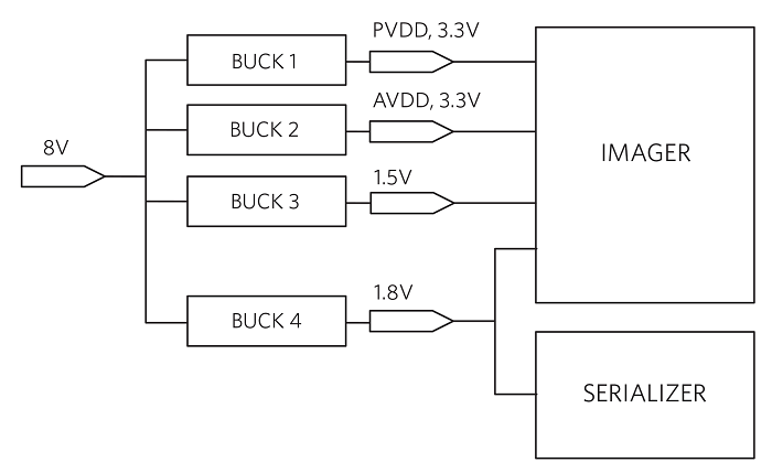 Fig. 1: Remote camera power-over-coax block diagram.
By covering the four rails with two high-efficiency dual-buck converter ICs, we save space and minimize losses. The dual buck converter shown at the top of Table 1 is an example of this application.
- How to shrink your ADAS ECUs
The smart car is loaded with ADAS electronic control units (ECUs), each taking power from the car battery. Each ECU supports a specific car function and has its own dedicated power management. With such a high level of variability, using a discrete approach to the ECU’s power management implementation might seem like the only option; that is, one ad hoc IC for each building block. However, this approach is incompatible with another important requirement of these ubiquitous devices, specifically small size. This section reviews three very different ECU applications and shows that even when multiple building blocks are required, a tailored integrated approach to power management can easily solve this dilemma.
- ADAS radar power solution
Fig. 2 shows a highly integrated solution that reduces the number of ICs down to two. The high-voltage (HV) buck converter withstands the load dump and takes the battery voltage down to 3.3 V, allowing for cold-crank operation near its output (well below 6 V). A high-density, low-voltage PMIC integrates the back-end voltage regulators. With this partitioning, the required area can be conveniently split into two chunks — one for the front-end buck converter (HV BUCK) and one for the PMIC — making it easy to “wrap” the power management solution around the signal-chain circuitry.
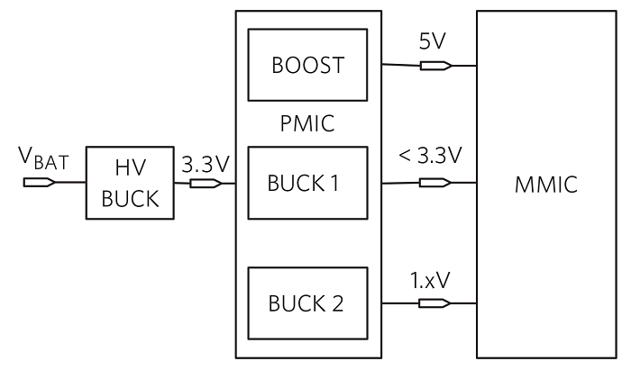
Fig. 2: ADAS radar PMIC.
If the ASIL compliance is handled by the microcontroller, a small PMIC having three high-efficiency, low-voltage DC/DC converter outputs will suffice. A front-end buck converter (HV BUCK) interfaces with the battery. Examples for the PMIC and front-end buck are provided in Table 1 under Radar. In this implementation, the total ADAS radar power management solution area is estimated to be 750 mm2 , or about one-third of the available area (versus half for the non-integrated solution).
- ADAS camera power solution
The previous partitioning solution can be replicated for an automotive camera ECU. Fig. 3 shows the PMIC inside the ECU, comprised only of an 8.5-V boost converter and a 1.8-V buck converter. The 1.8-V rail powers the microprocessor. The 8.5-V rail is routed through coaxial cables to power the remote cameras.
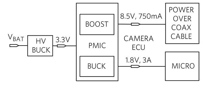
Fig. 3: Power PMIC inside the camera ECU.
A PMIC tailored for ADAS camera ECU applications, which integrates one sync boost and one step-down converter, is shown in Table 1 . The total solution area (PMIC + HV BUCK) is estimated to be about 550 mm2 .
- Instrument cluster power solution
The instrument cluster MCU processes the information displayed by the dashboard instrumentation. In Fig. 4 , the system-on-chip (SoC) microcontroller needs two power sources, 1.1 V to power its core and 1.8 V for the periphery. Here, the dual-buck PMIC shown in Table 1 under Cluster ECU fits the ADAS microprocessor core and periphery power-supply application. The total solution area (PMIC and HV BUCK) is estimated to be about 560 mm2 .
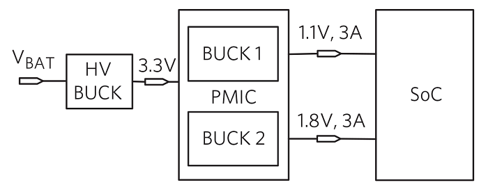
Fig. 4: Instrument cluster PMIC.
- Choose the right front-end buck converter for your automotive ECU
Gas-powered vehicles rely on a lead-acid battery to supply power to the electronic loads. The interface between the battery raw power and the delicate electronics requires a front-end regulator that can support different transient conditions.
The buck converter must withstand the battery voltage, which can be as high as 14.7 V on a fully charged battery. Vehicles employing start-stop technology experience large voltage dips when the engine starts, so the lower limit for the power source is well below the typical 12 V and can be as low as 4 V or lower. A high and well-controlled PWM switching frequency (above the AM band range of 500 kHz to 1.7 MHz) is required to reduce radio frequency interference, while spread spectrum is necessary to meet EMI standards.
If the ECU level of complexity is low, a simple, fully monolithic IC will suffice for the front-end buck converter. For current levels below 8 A, a monolithic solution can deliver the best efficiency in the smallest possible PCB area.
For medium- to high-level system complexity, requiring 8 A to 20 A of total current, the most convenient solution for the front-end buck converter is a controller IC plus external low-RDS(ON) MOSFETs. As an example, a 2.2-MHz synchronous step-down controller IC with 3.5-μA quiescent current is shown in Table 1 under cluster ECU front end. It is intended for applications with mid- to high-power requirements and currents up to 20 A.
For systems requiring a total current level above 20 A, a two-phase interleaved controller is the best solution for the front-end buck converter. A 2.2-MHz, single-output, two-phase interleaved or dual-output, single-phase synchronous step-down controller is also shown in Table 1 .
Safety and reliability
In this section, we will first discuss the safety of the electric path from the battery to remote cameras. Electric safety is enhanced using appropriate protectors and the adherence to ASIL-B and ASIL-D safety specifications. We will also review motorist safety. Visible LED drivers play a critical role in preserving and enhancing the sophisticated lighting patterns that improve motorist visibility. Similarly, IR LED drivers play an important role in DMS applications, checking the motorist’s state of alert. We will highlight the importance of power-efficient solutions that reduce heat generation and keep the electronics cool, thereby improving reliability.
- Providing a safe power path from the car battery to remote cameras
The current and voltage going into the camera modules via the coaxial cables must be monitored and controlled for various types of faults. Fig. 5 shows an example of a surround-view camera system. Here, a buck-boost converter connects to the battery and provides DC power to the remote cameras through a quad protector IC, a bank of AC-blocking coils (L), and four coaxial cables. A quad deserializer connects the microprocessor to the remote cameras via the bank of AC-coupling capacitors (C) and the same coaxial cables.
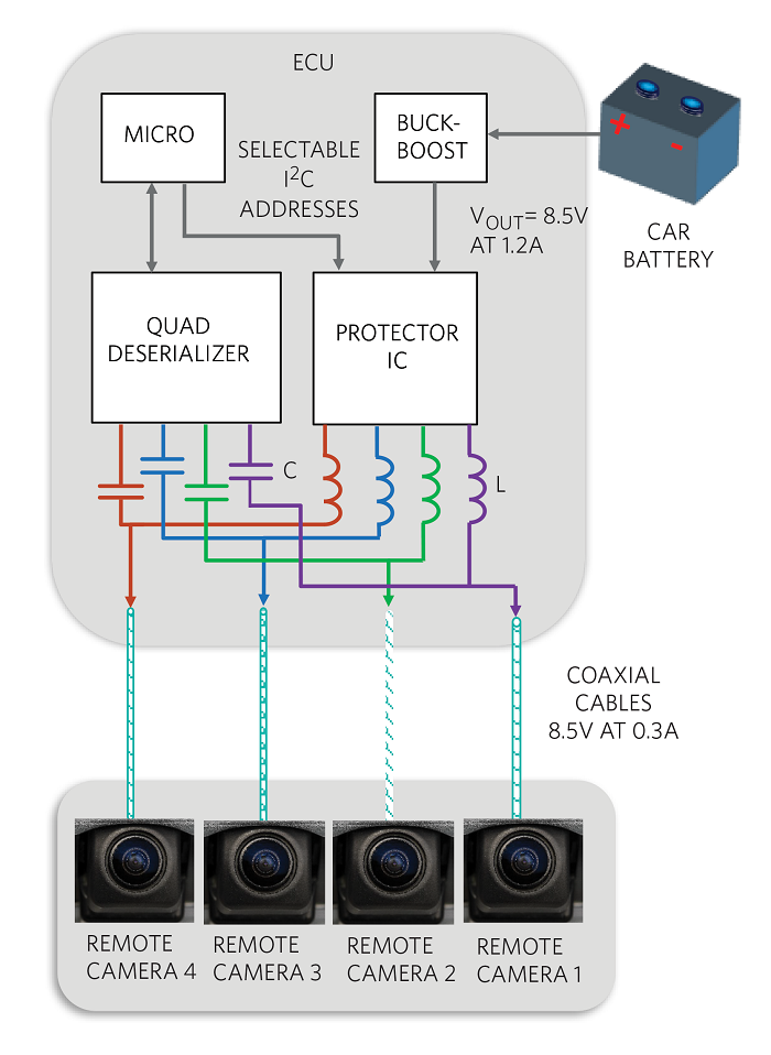
Fig. 5: Surround-view camera system.
As an example, a quad-power camera protector is shown in Table 1 under camera ECU front end. This ADAS IC effectively provides power and protection along the path from the car battery to the remote cameras.
- Achieve superior automotive exterior lighting with a high-power buck LED controller
LEDs have significant advantages over traditional technologies. The superior clarity of the white light in LED headlights (Fig. 6) improves driver reaction time. Adaptive front-lighting systems (AFS), enabled by LED matrixes, produce fast, complex light pattern changes that improve visibility for drivers in poor-light conditions.
At night, in response to the beams of an oncoming car, AFS can automatically adjust the light pattern, preventing the oncoming driver from being blinded by harsh lighting. The LED illumination rise time is twice as fast as that for incandescent sources so that LED-based brake lights illuminate quicker and provide advanced warning to drivers, increasing road safety.
Finally, LEDs consume less power than their incandescent counterparts, leading to substantial advantages in fuel consumption. LED controllers, the electronics that operate LEDs, play an important part in preserving and enhancing the inherent LED qualities of clarity, speed, and efficiency.

Fig. 6: LED-powered car headlight.
High-brightness LEDs (HB LEDs) require constant current for optimal performance. Because current must be kept constant to preserve color, the best dimming strategy for LEDs is pulse-width modulation (PWM), wherein the light intensity is modulated by time-slicing the current rather than by changing the amplitude. The PWM frequency must be kept above 200 Hz to prevent the LED from flickering.
With PWM dimming, the limit to the minimum LED “on/off” time is the time that it takes to ramp up/down the current in the switching regulator inductor. This may add up to tens of microseconds of response time, which is too slow for LED headlight cluster applications that require fast, complex dimming patterns. Dimming, in this case, can be performed only by individually switching on/off each LED in a string by means of dedicated MOSFET switches (SW1−K in Fig. 7 ). The challenge for the current control loop is to be fast enough to recover quickly from the output voltage transient due to switching in and out of the diodes.
Sophisticated headlight systems utilize a boost converter as a front end to manage both the variabilities of the input voltage (dump or cold-crank) and the EMI emissions. The boost converter delivers a well-regulated and sufficiently high output voltage (Fig. 7 ). Dedicated buck converters, working from this stable input supply, can then handle the complexities of controlling the lamp’s intensity and position by allowing each buck converter to control a single function, such as high beam, low beam, fog, daytime running lights (DRL), position, etc.
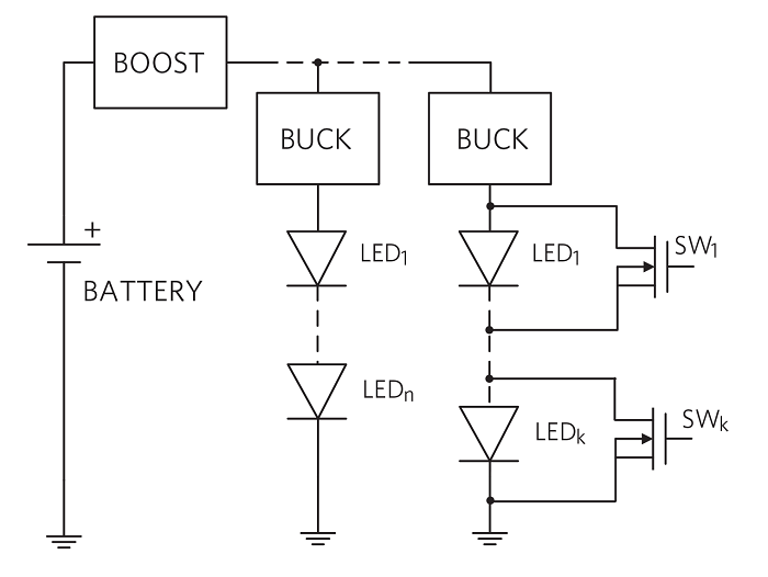
Fig. 7: Advanced LED lighting system.
An ideal solution should meet the requirements of a wide input voltage range, fast transient response, and high and well-controlled switching frequency, all while enabling high efficiency with synchronous rectification.
As an example, a buck LED controller enabling such a solution is shown in Table 1 under headlight ECU. For compact lighting applications with currents up to 2 A, a buck LED converter is an ideal solution. A fully synchronous 2-A step-down converter integrating two low-RDS(ON) 0.14-Ω (typ) MOSFETs and assuring high efficiencies up to 95% is also shown in the same section of Table 1 . The high level of integration yields minimum PCB area occupation. The boost converter in Fig. 7 can be implemented with the 36-V, 2.5-MHz automotive boost/SEPIC controllers shown in this same section of Table 1 .
- IR camera for DMS
Infrared (IR) cameras, utilizing an IR-LED diode in combination with a CMOS sensor, help recognize hazardous microsleep that affects motorists. The advantage of using infrared is its invisibility to the human eye and its ability to operate day and night. Image analysis processes information to determine if the driver is fatigued or distracted. With an IR-LED diode typical forward voltage of 2.8 V and a forward current of 1 A, the electronics that drives it is directly connected to the battery.
As an example, a buck LED driver is shown in Table 1 under IR DMS. The fully synchronous, 2-A step-down converter integrates two low-RDS(ON) 0.14-Ω (typ) MOSFETs, assuring high efficiencies up to 95%. With its 4.5-V to 65-V input supply range, the IC can easily withstand battery load dump, making it ideal as a front-end buck converter in DMS applications.
Power summary
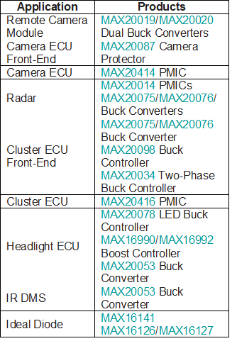
Table 1 is a summary of an example power management approach for ADAS.
Summary
ADAS technologies have the potential to improve driver safety and comfort and reduce car accidents and casualties. The adoption of ADAS technologies creates challenges in electronic solution size, safety, and reliability.
For each challenge, we showed examples of how power management can effectively help users realize ADAS systems. For the miniaturization challenge, we proposed highly integrated solutions for the remote camera module and for the camera, radar, and cluster ECUs. For better safety and reliability, we proposed solutions for lighting, ECU front ends, IR, and radar applications. Finally, for safety modules, we highlighted the availability of ASIL-qualified ICs. These power management solutions overcome the critical challenges faced by today’s ADAS implementations.
Advertisement
Learn more about Electronic Products MagazineMaxim Integrated


