By T.K. Hareendran, contributing editor
An oscilloscope is very useful when it comes to testing electronics but can also be very expensive. The introduction of minuscule, entry-level USB oscilloscope modules opens a new world of possibilities for ardent hobbyists, little makers, and entrepreneurs on a limited budget. The market is flooded with digital oscilloscope modules that sound so easy to use, you might well be suspicious that they’re more hype than help. But there really are plenty of good options.
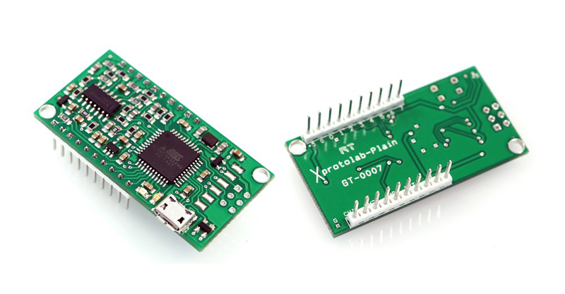
The $20 Xprotolab Plain from Gabotronics is one such good option. It’s a nifty little (1 x 2-in.) mixed-signal oscilloscope module blended with a logic analyzer and arbitrary waveform generator. Visualization of the signals and controlling the device can be done through an open-source PC interface software. The breadboard-compatible module with micro-USB interface can also be used as a development board for the AVR XMEGA microcontroller.
Hardware Overview
The key components of the Xprotolab Plain are:
- ATXMEGA32A4U: High-performance, low-power AVR XMEGA microcontroller (Atmel)
- TL064C: Low-power JFET quad-operational amplifier (STMicroelectronics)
- TPS60403: Unregulated 60-mA charge pump voltage inverter (Texas Instruments)
- AP7333-33: +3.3-V, 300-mA, low-dropout linear regulator (Diodes Inc.)
The module uses a USB interface to connect to a computer for control and data display, running under Windows, Linux, MacOS, and Android. Its technical performance specifications include:
As an Oscilloscope
- Analog Inputs: 2
- Maximum Sampling Rate: 2 Msps
- Analog Bandwidth: 200 kHz
- Resolution: 8 bits
- Input Impedance: 1 MΩ
- Buffer Size/Channel: 256 samples
- Input Voltage Range: −14 V to 20 V
As a Logic Analyzer
- Digital Inputs: 8 (3.3-V level)
- Maximum Sampling Rate: 2 Msps
- Frequency Counter: 16 Mhz
- Protocol Sniffer: UART, I2C, SPI
- Buffer Size: 256 samples
As an Arbitrary Waveform Generator
- Analog Output: 1
- Maximum Conversion Rate: 1 Msps
- Analog Bandwidth: 44.1 kHz
- Resolution: 8 bits
- Output Voltage: ±2 V
- Output Current: >±7 mA
- Buffer Size: 256 points
A complete feature list, user manual, interface software, technical support forum, and more are available on the manufacturer’s product page.
Initial Setup
The Xprotolab Plain comes with a pair of male-headers. The headers are relatively easy to solder by hand. For experimental purposes, the module can be mounted on a breadboard after the solder work, with a bunch of standard male-to-male jumper wires as the test probes.
To begin using the “scope,” you will need software. For MS Windows, first download and install the interface software (XScope) and device driver (WinUSB). After that, power up the module by connecting it to the PC’s USB interface. When the application starts, it will try to connect automatically.
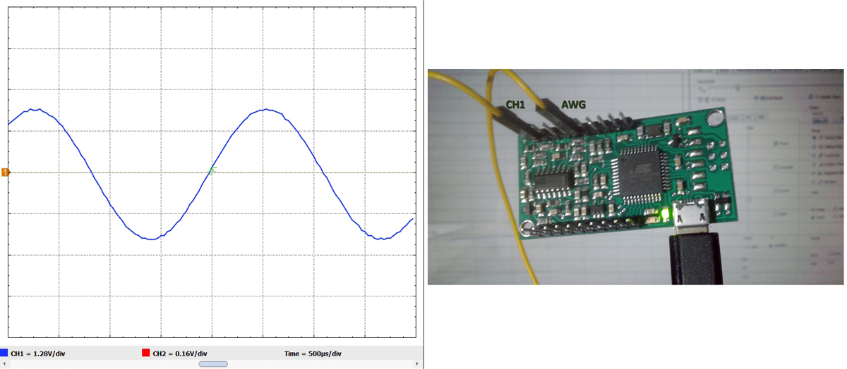
The next step is to connect the module’s AWG pin to CH1 through a jumper wire and observe the PC’s screen. It should look like the figure below. Once you are satisfied with your setup, remove the jumper wire and connect the scope’s inputs to the signals in your circuit from which you want to capture data.
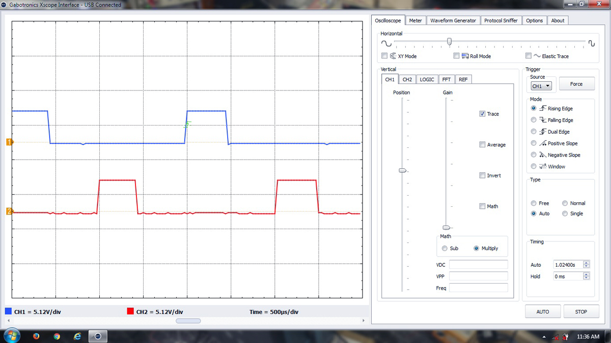
In my case, I currently have the Xprotolab Plain hooked up to a rather “dirty” prototype of a power electronics project. At the power project’s heart is an “Arduino Uno” microcontroller configured to render two “interleaved PWM” outputs. These signals are at the same frequency and pulse-width reference but with certain phase shift between them. I want to be able to monitor those signals as output power varies.
The image below is a random snap of the resulting display on a Windows 7 (x64) laptop. Looks nice to me! I also confirmed the accuracy of the display by comparing it with measurements by my more traditional (and expensive) benchtop GWInstek DSO (digital sampling oscilloscope).
I was slightly disquieted with a few things. For one, the interface software is not ultimately stable. It seems to freeze at times. Also, the logic level that the module works with is only 3.3 V. If you require a 5-V logic interface, you will need an add-on voltage translator chip (like the SN74LVC245A from Texas Instruments) to increase the input’s tolerance.
There is also a noise aspect to connecting via the 0.1-in. headers when measuring analog signals. What might be preferable would be to modify the module to use a coaxial cable terminated with a pair of standard BNC connectors. This can help trim down the noise on analog signals.
Manoj Patnaik, a Senior Consultant at TERI — The Energy and Resources Institute, New Delhi — took yet another approach, which he shared with me. His test gear with Xprotolab Plain at its core is shown in the figure below. He also shared his experience with the tool.
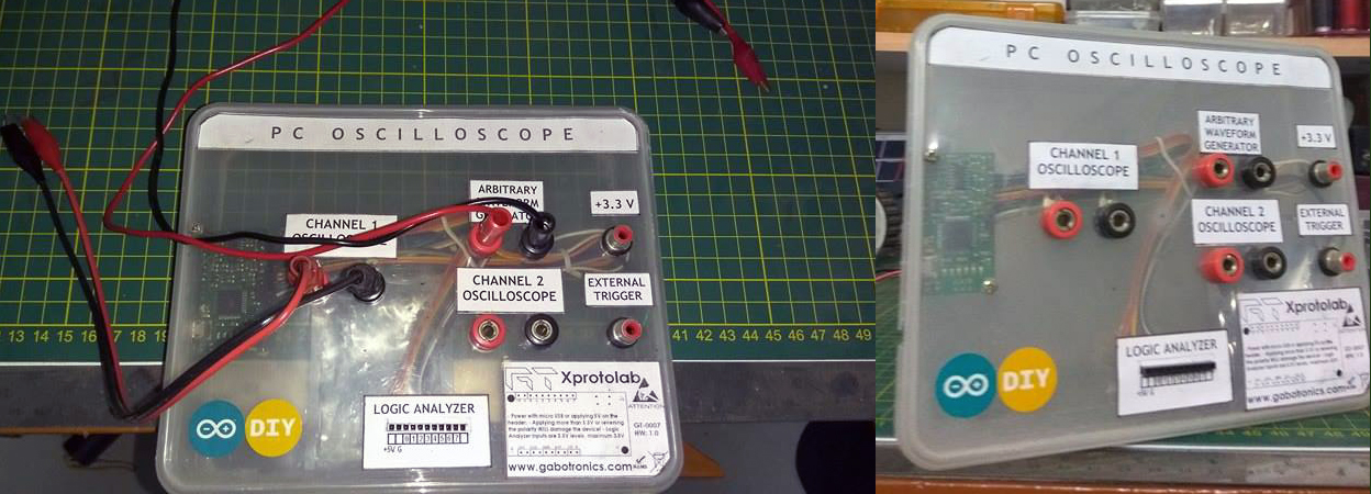
“I’ve been using the Xprotolab Plain for the last two years for my everyday basic hobby projects. It can’t be a replacement for a decent oscilloscope, but it’s surely a boon for tinkerers on a budget. It has two channels and a waveform generator, which is more than enough for folks to run a basic electronics lab at home. After the berg strips are soldered, it can be mounted onto a breadboard, or an enclosure can be built with banana jacks for connecting probes constructed with alligator clips, as I have done.
I have not used the logic analyzer much but have been using both channels and waveform generator for my projects. It works well on an MS Windows platform; however, I haven’t been successful so far with installing it on Ubuntu Linux, despite help from Gabotronics’ forums.
The only issue I face is the noise. Even when the probes are disconnected, there are visible fluctuations in the trace. But all in all, it’s a wonderful piece to have and a handy assistant to have on my bench. The only line of caution is that it may not handle more than 24 volts, and I don’t want to try going beyond it anyway.”
My experience matches that of Manoj. In my opinion, the Xprotolab Plain is an upright player, providing good results at a very low cost.
If you’re interested in obtaining a USB oscilloscope of your own for free (not the Xprotolab Plain, though), you can enter the drawing at our sister site, EEWeb: EEWeb is giving away the world’s smallest mixed-signal USB oscilloscope
And for more of TK’s hands-on reviews, follow these links:
Hands-on review: Digistump Oak dev board provides Wi-Fi for everything IoT — The capable yet low-cost Oak from Digistump is a compact Wi-Fi module that can truly be a boon for experimenters and makers.
Hands-on review: jailbreaking a timer to create an MCU development platform — A standalone module intended for another purpose can yield a development platform richer with resources for a much lower cost.
Hands-on review: Sparky single-board computer for media, VoIP, and standalone computing — With new technologies, products, and standards being released every day, makers and experimenters need help getting projects up and running quickly.
Advertisement